32 | Regency
®
U39-10 ULTIMATE Direct Vent Freestanding Gas Stove
|
32
installation
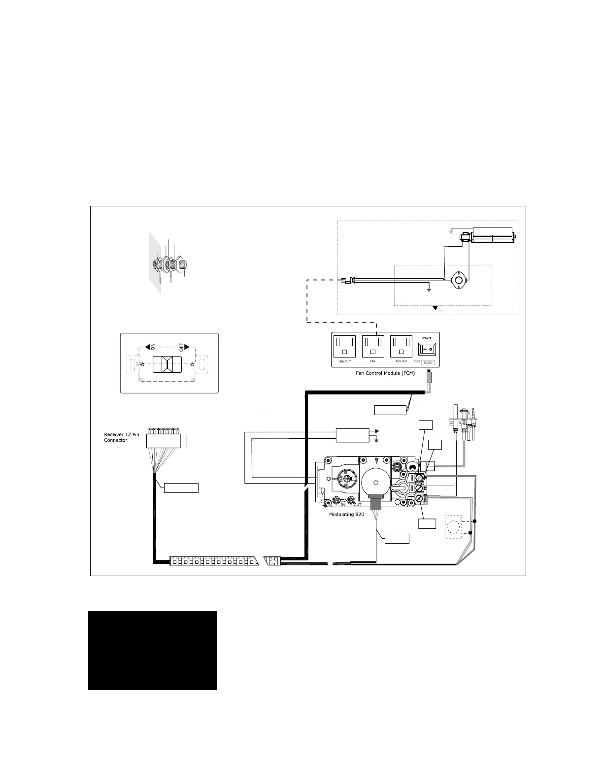
WIRING DIAGRAMS
This heater does not require a 120V A.C. supply
for operation. In case of a power failure, the
burner switch and the optional remote control/
thermostat will continue to operate. However, a
120V A.C. power supply is needed for the fan/
blower operation.
(Do not cut the ground terminal off under
any circumstances.)
NOTE: Even if the fan is not purchased
with the unit, it is still a good idea to
bring power to the receptacle box
(provided with the unit) in case the
fan is installed at a later date.
Caution: Ensure that the wires do
not touch any hot surfaces and are
away from sharp edges.
CAUTION: Label all wires
prior to disconnection
when servicing controls.
Wiring errors can cause
improper and dangerous
operation.
ENGLIS
REMOTE
TP
TH
TPTH
MOTOR
RECEIVER
FCM-COM
Green
White
Red
Black
(+)
(-)
Ground
Green
Neutral
Black
Fan Thermodisc
(Normally Open)
Ground
120V AC
60 Hz
Fan
White
Thermodisc Cage
Live
Thermostat
(Optional)
(Millivolt)
DC
Spark Box
To
Electrode
Lockwasher
Fan
ground
Power
cord
ground
wire
Star
washer
Nut
Nut
#8 Ground Lug
Star
washer
Receiver Hearth Mount