Regency
®
U39-10 ULTIMATE Direct Vent Freestanding Gas Stove | 33
33
|
installation
Thermostat Wire Table
OPTIONAL WALL
THERMOSTAT
A wall thermostat may be installed if desired.
Connect the wires as per the wiring diagrams.
Note that the wires are connected to the "TH" on
the gas valve. Use table below to determine the
maximum wire length:
Note: Preferable if the thermostat is installed
on an interior wall.
Regency
®
offers an optional programmable
thermostat but any 250-750 millivolt rated non-
anticipator type thermostat that is CSA, ULC or
UL approved may be used.
CAUTION
Do not connect the millivolt
wall thermostat wires
to the 120V wires.
FINAL CHECK
Before leaving this unit with the customer, the
installer must ensure that the appliance is ring
correctly. This includes:
1. Clocking the appliance to ensure the correct
ring rate (rate noted on label) at 15 minutes.
2. If required, adjusting the primary air to ensure
that the ame does not carbon. First allow the
unit to burn for 15 min. to stabilize.
3. Check for proper draft.
CAUTION
Any alteration to the product that causes
sooting or carboning that results in damage
to the exterior facia is not the responsibility
of the manufacturer.
Recommended Maximum Lead Length
(Two-Wire) When Using Wall
Thermostat (CP-2 System)
Wire Size Max. Length
14 GA. 50 Ft.
16 GA. 32 Ft.
18 GA. 20 Ft.
20 GA. 12 Ft.
22 GA. 9 Ft.
DC SPARK IGNITER
BATTERY INSTALL
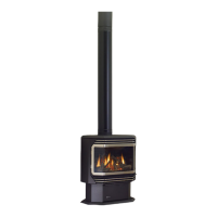
3. Remove four screws to remove the access
panel (in locations shown below) and the
chain attached to the front door and the unit.
Remove chain
here
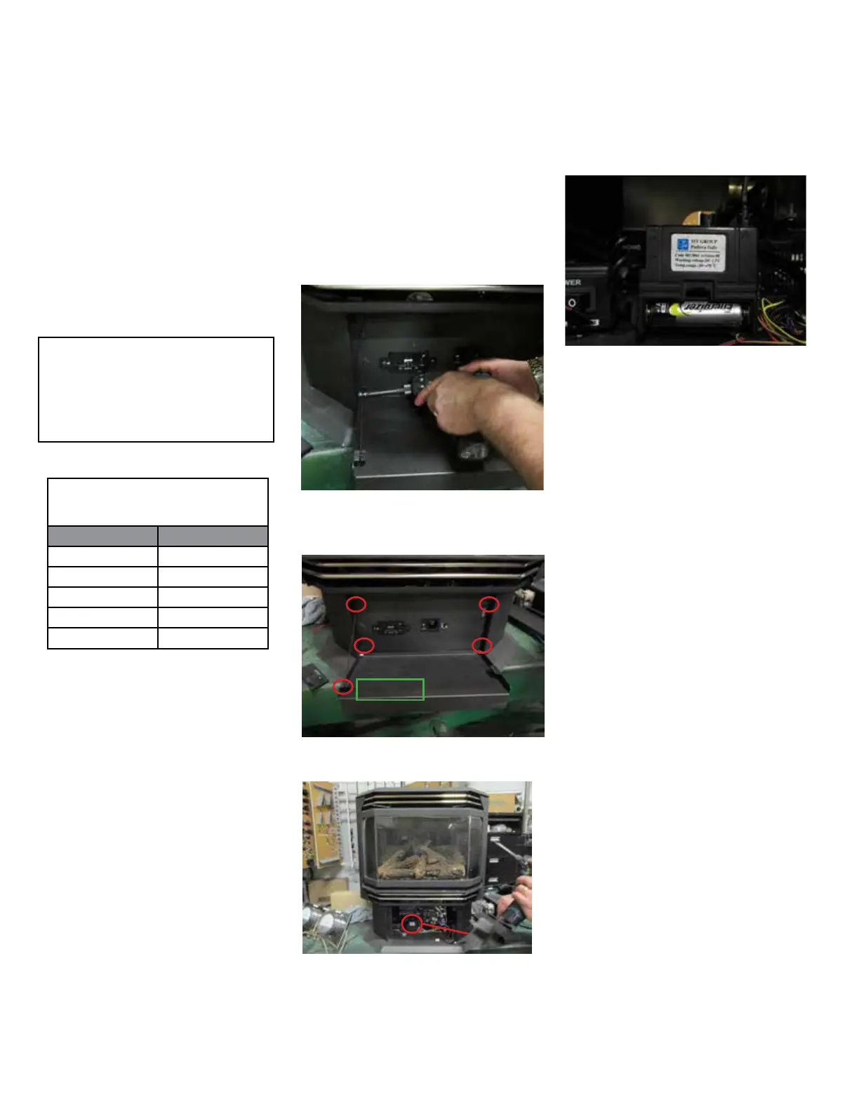
Install supplied battery into the DC spark box.
1. Open pedestal front door.
2. Remove 2 screws that secure the front door
to the unit. One screw is on the left hand side
and the other on the right hand side. (Left side
shown).
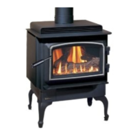
4. The DC spark box will be exposed after re-
moving the valve cover.
DC Spark Box
5. Open the battery compartment door on the
DC spark box
6. Install battery into DC spark box.
7. Reverse steps 1 to 5.