3 Interpretation of machine indications and symbols
3.1 The REHM control panel
3.1.1 Summary
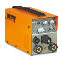
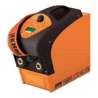
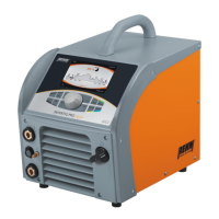
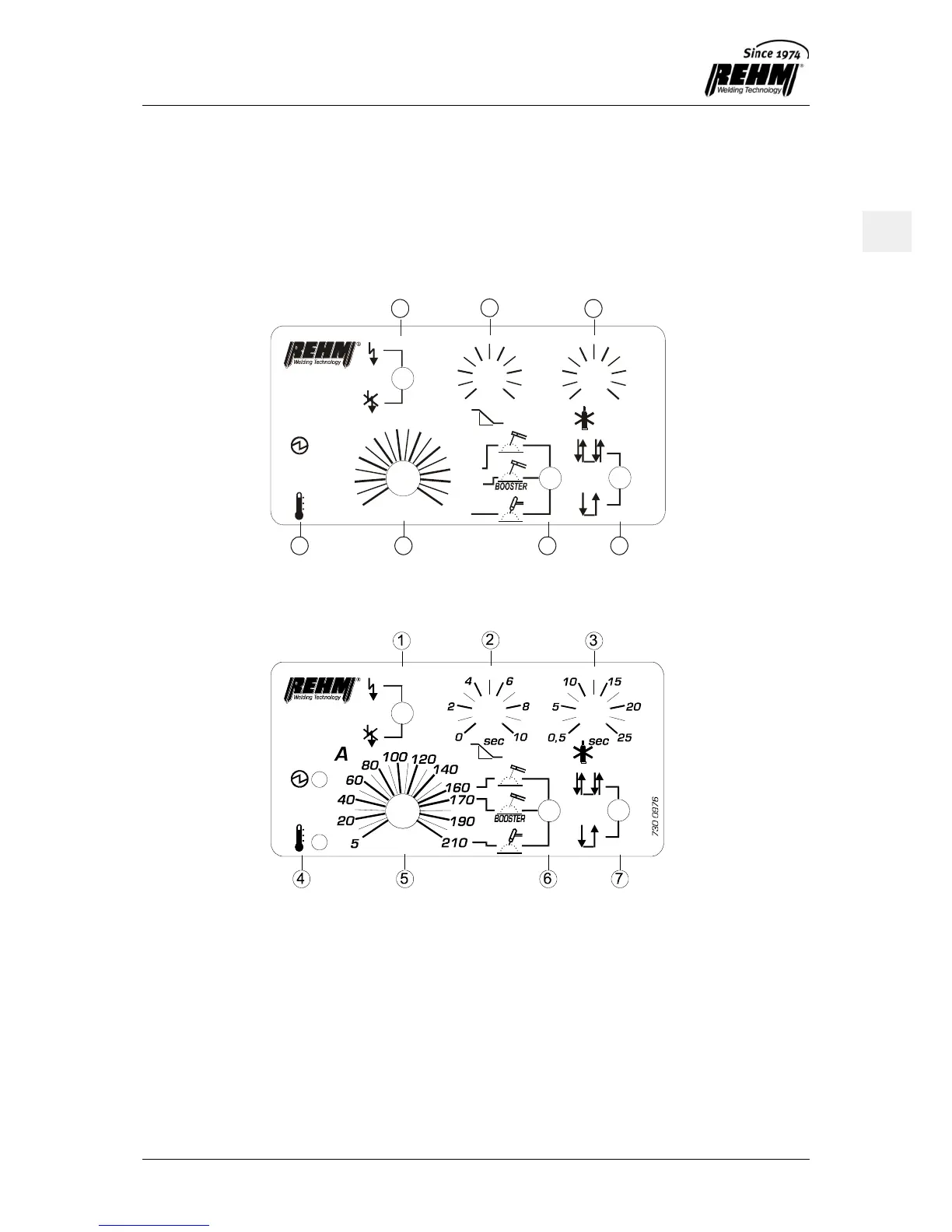
The TIG welding unit is operated using the REHM control panel shown in Fig. 3.1 and Fig. 3.2.
Fig. 3.1 TIGER 170 control panel
Fig. 3.2 TIGER 210 control panel
The control panel is divided into the following areas:
Selector switch HF ignition unit (On/Off)
Downslope time
Post-flow gas time
Indicator lamps for over-temperature and ready for operation
Setting control for welding current
Mode selection switch for: TIG, Stick-electrode, and Booster-Function
Function selection switch for latch and non-latch torch trigger modes