Do you have a question about the REHM TIGER 170 DC and is the answer not in the manual?
Introduction and thanks for purchasing a REHM TIG/Stick-electrode welding unit.
Overview of the TIGER welding unit's capabilities, design, and intended use.
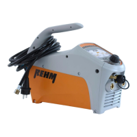
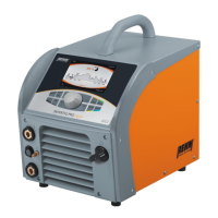
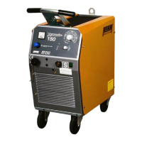
Highlights the TIGER's power, portability, robust housing, inverter design, and IP23 classification.
Explains the basic principle of TIG welding using tungsten electrodes and inert gas.
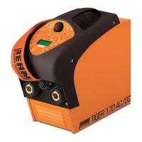
Details the types of metals that can be welded with TIGER DC and AC/DC units.
Describes how TIG welding operates, including arc establishment and shielding gas.
Provides guidelines on the correct application and user qualifications for REHM welding units.
Explains typographical markings and safety symbols used within the manual.
Defines warning symbols and their meaning for potential hazards to life and limb.
Identifies specific warning symbols found on the welding unit itself.
Covers general safety regulations, compliance, and requirements for the power supply.
Explains the simple, quick, and safe operation using a single control knob.
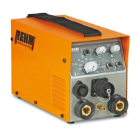
Details the layout and components of the welding unit's control panel.
Provides an overview of the operator panel and its protected design for arduous environments.
A table detailing the symbols, their meaning, and corresponding chapter references.
Describes features like parameter storage, relevant parameter display, and special mode activation.
Explains the specific functions controlled by the operator panel elements.
Details how to set the welding current 11 and includes a warning for a quick setting method.
Explains setting pulse time t1 for conventional and high frequency pulsing.
Describes setting welding current 12 for TIG welding and dual current level control.
Explains setting downslope time and how manual pulsing is achieved with torch trigger.
Details the setting of gas post-flow time to protect the weld pool after arc extinguishes.
Explains how to set and use direct current (DC) welding modes.
Describes setting and using alternating current (AC) welding for Aluminium alloys.
Explains wave balance settings for AC welding to influence arc and cleaning effect.
Details setting AC frequency for optimal arc stability and performance.
Explains the 4-step trigger mode for reduced operator fatigue during TIG welding.
Describes the 2-step trigger mode for fast tacking and spot welding.
Explains the standard high voltage ignition for contact-free arc striking.
Details the Lift Arc function for contact ignition, useful near sensitive electronics.
Explains the Booster mode for stick welding, deactivating mains current monitoring.
Describes the Fuse Hold mode for monitoring mains current and preventing fuse tripping.
Details TIG welding parameters, arc establishment, and shielding gas usage.
Introduces the special mode for accessing and altering numerous parameters and functions.
Overview of special mode functions like pre-flow time, ignition energy, and program save/load.
Explains the pre-flow gas time setting and its role in protecting the electrode.
Details the variable ignition energy settings for Lift Arc and HF ignition modes.
Describes setting the start current for controlled arc striking and heat management.
Explains the time taken for the welding current to rise linearly from start to set current.
Details setting the crater fill current to prevent seam cracking at weld termination.
Explains the hot start function for improved ignition in stick-electrode welding.
Describes the Arc Force function for stable arc and smooth droplet transfer in stick welding.
Details how to save and load up to 99 different machine setting programs.
Explains the Dual Wave process combining AC and DC for better pool control in Aluminium welding.
Provides an overview of the status indications given by the machine's control LEDs.
Describes the three-digit display for parameter selection and real-time status.
Details the single control knob for parameter selection, alteration, and confirmation.
Explains the Anti-Stick function that limits current during short circuits to prevent electrode damage.
Describes INTIG-Energy for automatic ignition energy selection for HF and Lift-Arc.
Explains the EPC system for monitoring mains voltage and protecting the machine.
Instructions on how to reset the machine to factory default parameters.
Details the foot pedal for remote current adjustment and its operational modes.
Explains the operation using the foot pedal in the 2-step mode.
Describes controlling current via foot pedal, suitable for stick welding.
Describes the hand remote for current alteration, primarily for stick-electrode welding.
Details TIG torches with remote control for adjusting welding current from the handle.
Describes the TIGER set including machine, torch, gas regulator, and carrying case.
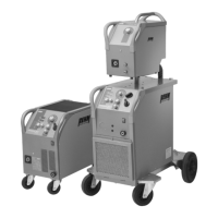
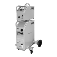
Details the water cooler for use with water-cooled TIG torches at higher currents.
Specifies the adapter cable required for connecting remote controls to the machine.
Explains the mechanised welding option for automated applications via the torch socket.
Emphasizes reading safety instructions before initial use and operation.
Details compliance with regulations and safety for high electrical hazard environments.
Instructions on positioning the unit for optimal operation and safety.
Provides instructions for connecting the welding unit to the mains power supply.
Details requirements for proper ventilation to ensure cooling and performance.
Offers advice for personnel working with welding power sources.
Explains how to connect torch and electrode holder cables using quick-action connections.
Provides recommended cross-sections for copper leads based on current and length.
General safety warnings for operating personnel and the environment.
Highlights electrical safety precautions during connection and maintenance.
Provides safety instructions regarding arc radiation, protective clothing, and gas cylinders.
Details precautions to prevent fires caused by sparks or hot slag during welding.
Emphasizes the need for fume extraction and proper workplace ventilation.
Lists checks to be performed before switching on the unit for operation.
Provides instructions for correctly connecting the earth cable for effective grounding.
Offers practical advice on TIG welding materials, tungsten electrodes, and arc characteristics.
Emphasizes safety procedures when a fault occurs and work must be stopped.
A table listing possible causes and remedies for various operational issues and error messages.
Highlights safety precautions for maintenance personnel and the use of original spares.
A table outlining recommended actions and intervals for preventative maintenance.
Instructions for cleaning the internal components of the welding unit.
Guidance on environmentally compatible disposal of electrical tools according to EU directives.
A detailed table of components and their corresponding article numbers for each TIGER model.
Photographs illustrating the location of various machine components with labels.
| Brand | REHM |
|---|---|
| Model | TIGER 170 DC |
| Category | Welding System |
| Language | English |