Installation, start up and operating manual – version 5.3 Gen.10
Radio control BRICK and PAIL
Information regarding the receiver’s joysticks’ relay contacts is included in
TECHNICAL SPECIFICATIONS.
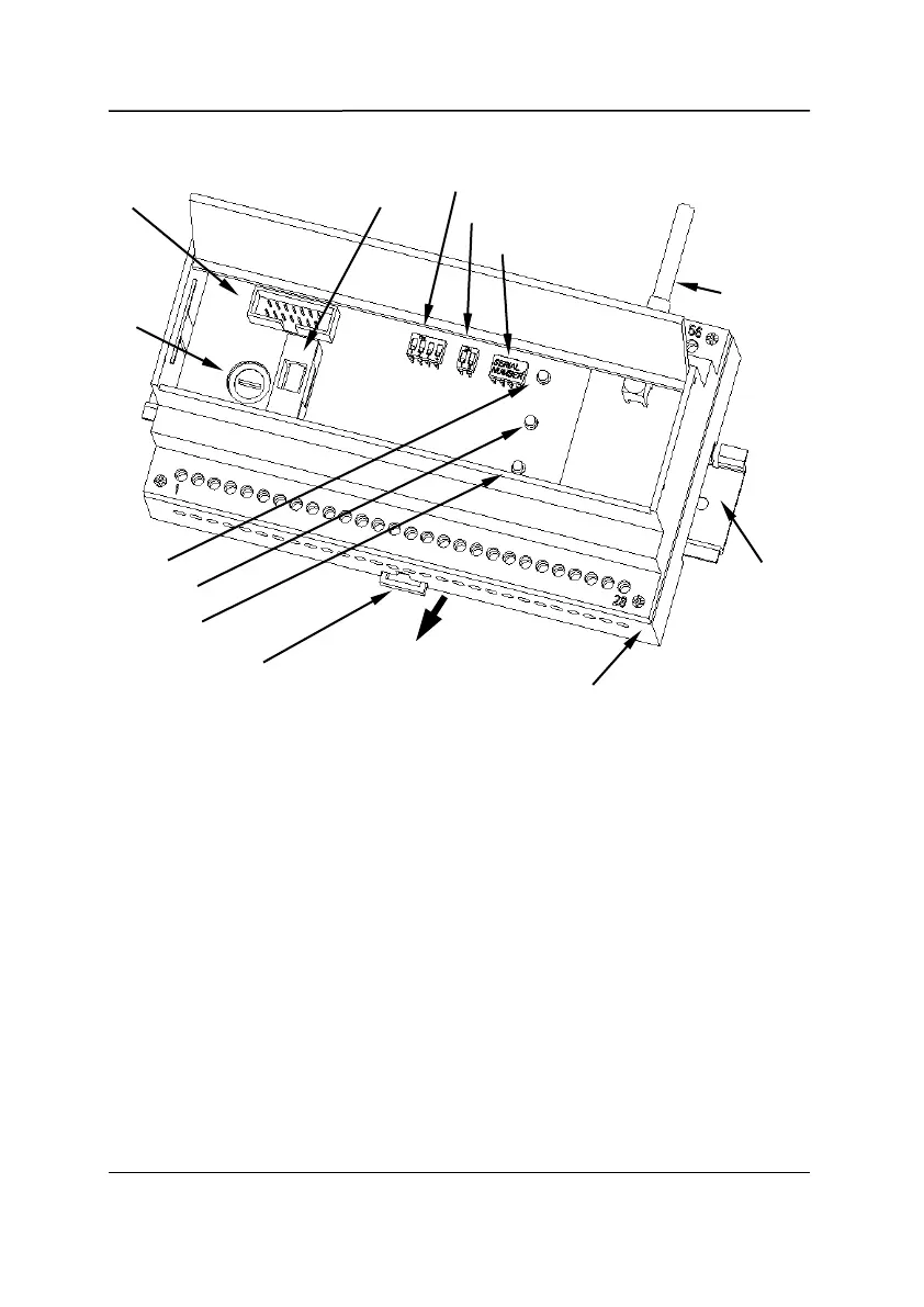
Electrical current supply is confirmed by the continuous ON led located on
the receiver module.
The connection between the radio control unit and the machine’s electric
panel must be completed so that if the radio control unit loses contact
with the machine, control can be taken over using the cabled keypad.
The multiple control of a machine using both the radio control unit and
cabled keypad at the same time is NOT permitted. Pay special attention
to the connection of the EMERGENCY STOP circuit by following the
machine’s original electric diagram to wire it up in the correct way.
STOP
FUSE
SUPPLY
FUSE
RECEIVER
UNIT
ANTENNA
12 REMdevice
®
- ITALY