Installation, start up and operating manual – version 5.3 Gen.10
Radio control BRICK and PAIL
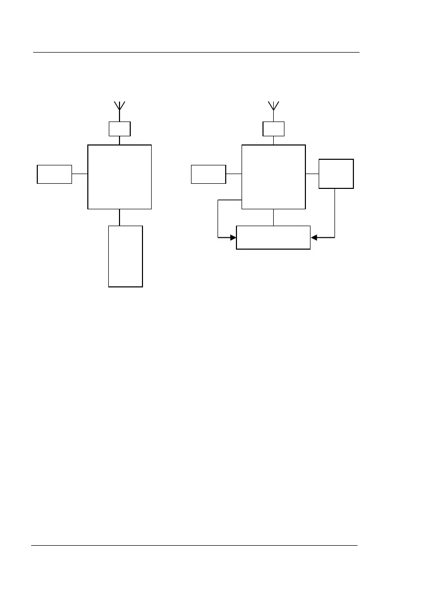
ELECTRIC CIRCUITS BLOCK DIAGRAM
Transmitter Receiver
Description of transmitter
The commands issued via the transmitter unit are processed by the
microprocessor that constructs the linking telegram that includes a
unique code and sends it to the TX module of the radiofrequency
transmission.
Description of receiver:
The linking telegram received by the reception RX module is processed
by the μP A microprocessor which verifies its authenticity by comparing it
with the uniquely valid code. If the commands are correct the
microprocessor will activate the corresponding relay.
In the event of active or passive emergency commands, broken or lack of
radio signal, the μP A microprocessor stops the machine being operated
(safety system 1).
The μP B microprocessor controls the proper functioning of the μP A
microprocessor. It will intervene in the event of failure within the
command and safety relays (safety system 2).
code
Keypad or
joystick
μP
code
μP A
μP B
Relay
2
REMdevice
®
- ITALY
33