17
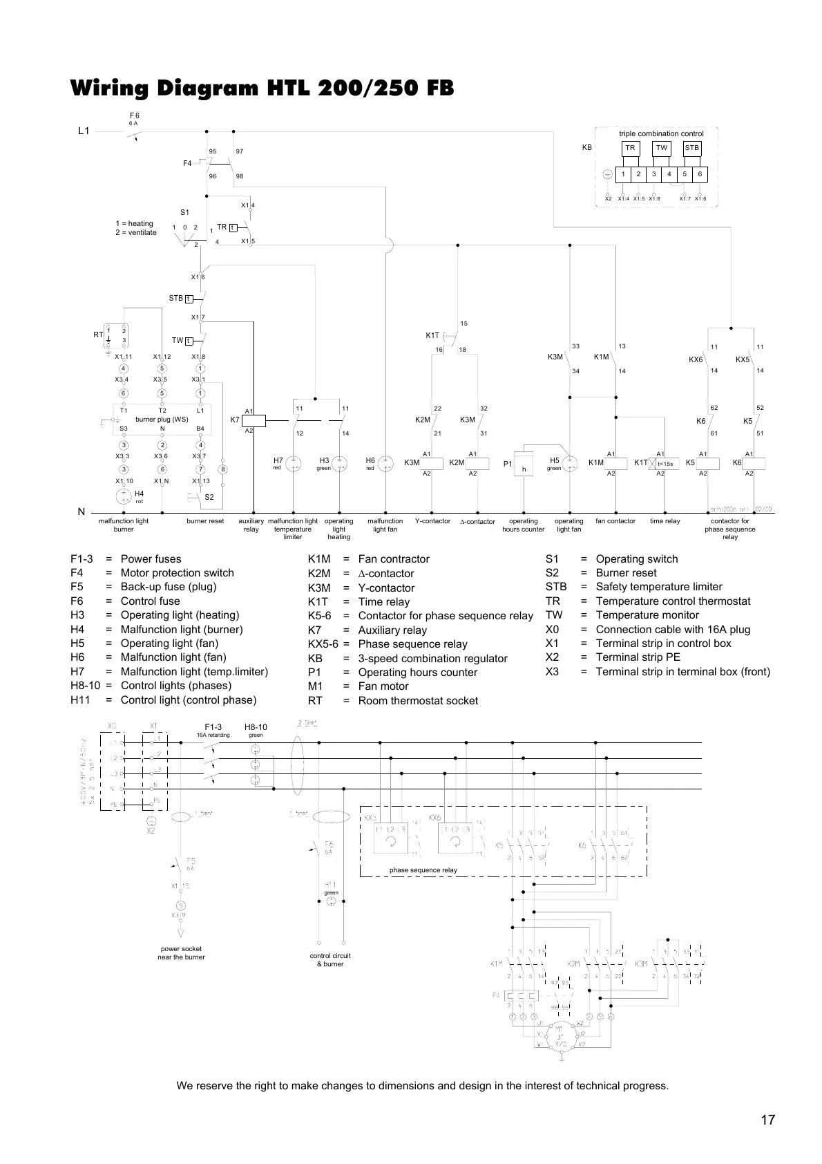
Wiring Diagram HTL 200/250 FB
F1-3 = Power fuses
F4 = Motor protection switch
F5 = Back-up fuse (plug)
F6 = Control fuse
H3 = Operating light (heating)
H4 = Malfunction light (burner)
H5 = Operating light (fan)
H6 = Malfunction light (fan)
H7 = Malfunction light (temp.limiter)
H8-10 = Control lights (phases)
H11 = Control light (control phase)
K1M = Fan contractor
K2M = ∆-contactor
K3M = Y-contactor
K1T = Time relay
K5-6 = Contactor for phase sequence relay
K7 = Auxiliary relay
KX5-6 = Phase sequence relay
KB = 3-speed combination regulator
P1 = Operating hours counter
M1 = Fan motor
RT = Room thermostat socket
S1 = Operating switch
S2 = Burner reset
STB = Safety temperature limiter
TR = Temperature control thermostat
TW = Temperature monitor
X0 = Connection cable with 16A plug
X1 = Terminal strip in control box
X2 = Terminal strip PE
X3 = Terminal strip in terminal box (front)
We reserve the right to make changes to dimensions and design in the interest of technical progress.
t
t
102
K3M K1M K6
H7 H3 H6 H5
grün
P1
h
K2M
15
1
4
K3M K1M
N
L1
F4
K1T
STB
A1
A2
A1
A2
A1
A2
A1
A2
A1
A2
A1
A2
X1 5
X1 4
X1 6
TR
2
rotgrünrot
K5K2M
K3M
D-Schütz Phasenfolge
Relais
ZeitrelaisVentilator
Schütz
Betriebslampe
Ventilator
Betriebs-
stunden-
zähler
123456
X1:4 X1:5 X1:8 X1:7 X1:6X2
STBTWTR
KB
K1T
t<15s
Störlampe
Brenner
Y-SchützStörlampe
Ventilator
Betriebslampe
Heizen
Störlampe
Temperatur-
begrenzer
Dreifach-Kombinationsregler
KX6 KX5
K6 K5
F6
6A
11 11
14 14
62 52
61 51
34 14
33 13
95 97
9896
12 14
1111
16 18
22 32
21 31
63
X1 NX1 10
t
2
1
3
H4
RT
154
X1 8X1 12X1 11
TW
rot
X3 1X3 5X3 4
156
Brennerstecker (WS)
23
L1T2T1
X3 6X3 3
7
X1 13
4
X3 7
S3 B4N
X1 7
S1
1=Heizen
2=Lüften
8
S2
Brenner-
Reset
K7
A1
A2
Hilfsrelais
1 = heating
2 = ventilate
malfunction light
burner
burner reset auxiliary
relay
operating
light
heating
malfunction light
temperature
limiter
malfunction
light fan
operating
hours counter
operating
light fan
fan contactor contactor for
phase sequence
relay
burner plug (WS)
red
red green green
triple combination control
time relay
∆-contactor
Y-contactor
phase sequence relay
control circuit
& burner
power socket
near the burner
green
F1-3
16A retarding
H8-10
green