PE
-Pin.2
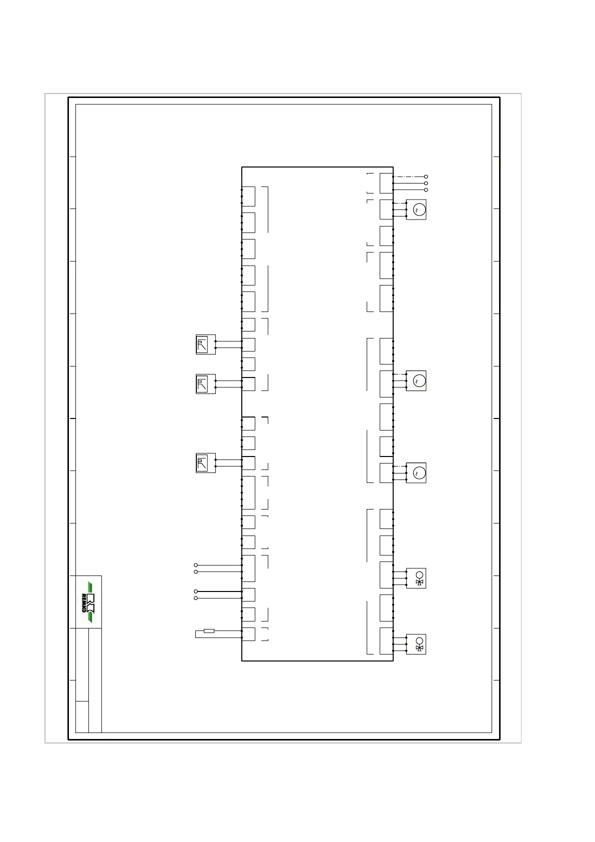
Spannungsversorgung 230V
-> SMT I/O1 (unten) Pout2
N L
1
M
PE
N
L
-Pout1.2
Versorgung 230V
Interne Pumpe A43.2
U
t
-
+
-A41.2
Signal 0-10V / PWM
3. gem. Kreis
1
M
PE
N
L
-A13.2
Pumpe 230V
4. gem. Kreis
U
t
-
+
-A43.2
Signal PWM
Interne Pumpe
tuptuO rotautcAtuptuO rotautcAtuptuO rotautcArewoP Actuator Supply
cRsecafretnI suBsecafretnI TOIPSlangiS rotautcAlangiS rotautcAstupnI rosneS
Systemregler SMT I/O
1.PE
1.N
1.L
2.PE
2.N
2.L
3.PE
3.N
3.L
PE
N
A10
L
PE
N
A11
L
PE
N
A12
L
PE
N
A13
L
PE
N
A14
L
PE
N
A01
PE
N
A02
PE
N
A03
PE
N
A04
PE
N
A20
A21
PE
N
A22
A23
PE
N
A24
A25
S25
+5V
GND
S26
+5V
GND
S27
+5V
GND
S28
+5V
GND
S29
+5V
GND
GND
A40
GND
A41
GND
A42
GND
A43
GND
A44
GND
A45
GND
A46
MI
MO
CLK
nSS
GND
OT1
OT1
OT2
OT2
+12V
B1
A1
GND
B2
A2
B
3
A3
R
GND
-SMT2.1
Systemregler (unten)
U
t
-
+
-A46.2
Signal 0-10V / PWM
4. gem. Kreis
1
M
PE
N
L
-A02.2
Pumpe 230V
3. gem. Kreis
B1
-SMT1.1
Kommunik. Master
-> SMT I/O 1 (unten)
A1
M
N
Auf
Zu
-A20.2/A21.2
Mischventil 230V
3. gem. Kreis
B
-AM2
Kommunik. AM2
-> Außenmodul 2 (bauseits)
A
1
2
-RC.2
Kodierwiderstand
Geräteabhängig
M
N
Auf
Zu
-A24.2/A25.2
Mischventil 230V
4. gem. Kreis
Kodierwiderstand:
WKF Slave -> 160 OhmWKF Slave -> 160 Ohm
0 1 2 3 4 5 6 7 8 9 10 11
4/6
WKF DUO 2021
0 1 2 3 4 5 6 7 8 9 10 11
04.03.2021
Projekt Titel:
Power supply 230V
Internal pump A43.2
Power supply 230V
Signal 0-10V / PWM
Signal PWM
-> SMT I/O1 (bottom) Pout2
3rd mixed circuit
Internal pump
Pump 230V
Mixed valve 230V
Pump 230V
4th mixed circuit
3rd mixed circuit
3rd mixed circuit
Mixed valve 230V
4th mixed circuit
Project title:
-Pout1.2
Power Actuator Supply
Actuator Output Actuator Output
Actuator Output
System controller (bottom)
Actuator Signal Bus Interfaces
System controller SMT I/O
Actuator Signal
Signal 0-10V / PWM
4th mixed circuit
Communic. AM2
Coding resistor
-> Outdoor unit 2 (provided by the customer)
Device-dependent
OT InterfacesSPI
Coding resistors:
WKF Slave -> 160 Ohm
Communic. Master
-> SMT I/O 1 (bottom)
-Pin.2

 Loading...