Renesas RA Family EK-RA2E1 – Quick Start Guide
R11QS0035EG0100 Rev.1.00 Page 21 of 26
Jan.04.21
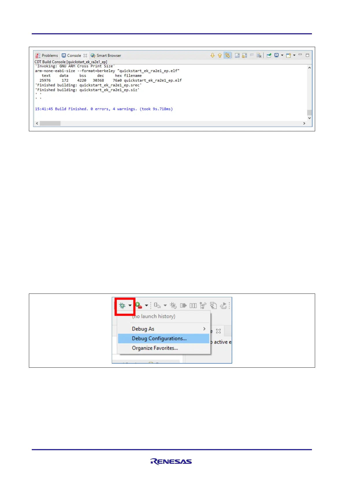
6. A successful build produces an output as follows.
Figure 20. Successful Build Output
5.4 Setting Up Debug Connection Between the EK-RA2E1 board and Host PC
To program the modified Quick Start example project on to the EK-RA2E1 board, a debug connection is
necessary between the EK-RA2E1 board and host PC.
1. Connect the USB cable from the PC to the micro-B USB debug port (J10) of the EK-RA2E1 board as
shown earlier in Figure 3.
Note: The EK-RA2E1 board supports 3 debugging modes. In this section and the following sections,
default debugging mode, Debug On-Board, is used. More information on debugging modes is
available in EK-RA2E1 user’s manual.
2. Verify that the debug LED (LED5) stops blinking and lights up orange indicating that the J-Link drivers
are detected by the EK-RA2E1 board.
Note: The debug LED (LED5) continues to blink when J-Link drivers are not detected by the EK-RA2E1
board. In that case, make sure that the EK-RA2E1 board is connected to the host PC through the
micro-B USB debug port (J10) and that J-Link drivers are installed on the host PC by checking in
the Windows Device Manager (expand Universal Serial Bus controller, and locate J-Link
driver).
5.5 Downloading and Running the Modified Quick Start Example Project
1. In e
2
studio, click the drop-down menu for the debug icon, select Debug Configurations option.
Figure 21. Selecting the Debug Option

 Loading...


