Renesas RA Family EK-RA2E1 – Quick Start Guide
R11QS0035EG0100 Rev.1.00 Page 9 of 26
Jan.04.21
4. Running the Quick Start Example Project
This section lists the requirements and instructions to power up the EK-RA2E1 board and run the Quick Start
example project.
Hardware Requirements
• EK-RA2E1 board
• Micro USB device cable
• A PC with at least 1 USB port
Software Requirements
• Windows
®
10 operating system
• SEGGER J-Link
®
USB Serial Drivers
• SEGGER J-Link Real-Time Transfer (RTT) Viewer, virtual terminal emulation application. It is included in
J-Link Software and Documentation Pack which can be download from segger.com
4.1 Connecting and Powering Up the EK-RA2E1 Board
1.
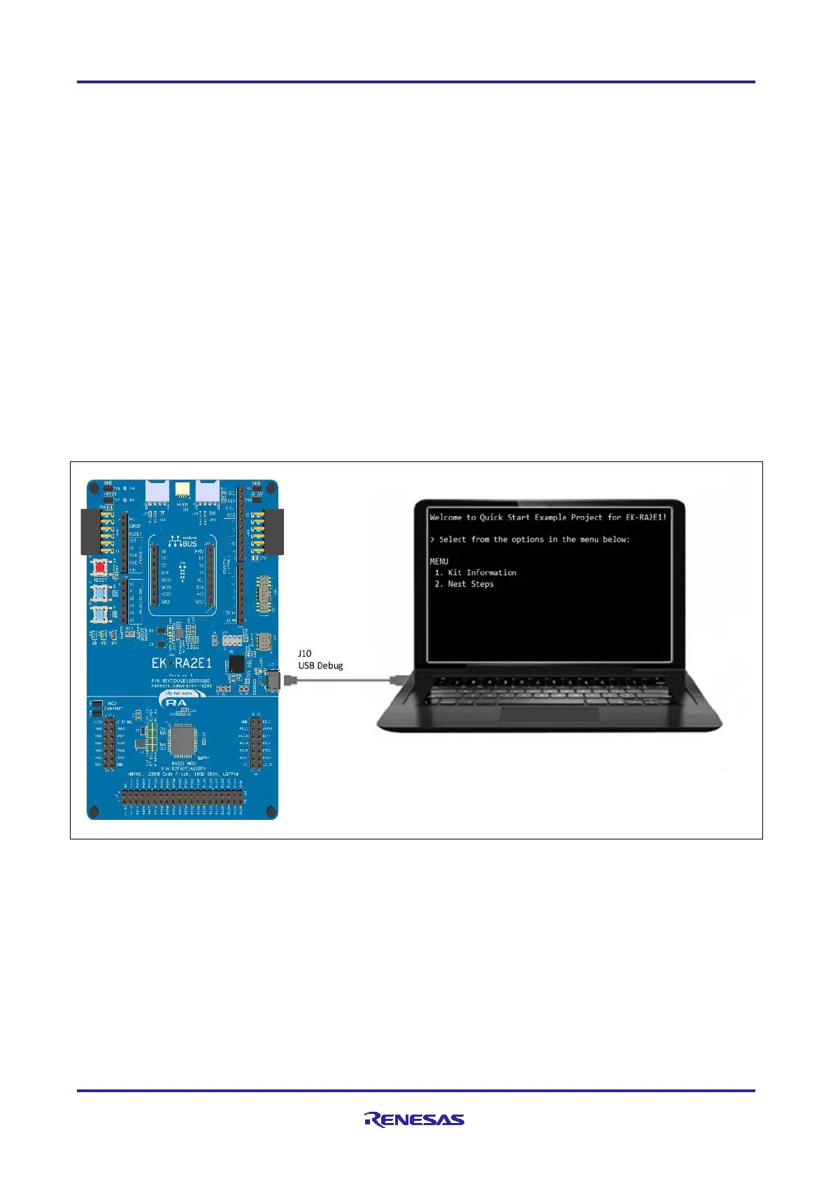
Connect the micro USB end of the micro USB device cable to micro-AB USB Debug port (J10,
DEBUG1) of the EK-RA2E1 board.
2.
Connect the other end of this cable to the USB port of the host PC. Power LED (LED4) on the EK-
RA2E1 board lights up white, indicating that the EK-RA2E1 board is powered on.
Figure 3. Connecting the EK-RA2E1 Board to the Host PC via USB Debug Port J10
4.2 Running the Quick Start Example Project
To run the Quick Start example project, use the following instructions:
1. On power up or RESET, the three user LEDs will take on the following states:
LED1 Blue - Blinking at 1 Hz frequency and at 10% intensity
LED2 Green – Steady, full intensity
LED3 Red – Off
Note: The debug LED (LED5) will blink or light up orange indicating communication between host and
device.

 Loading...


