Renesas RA Family EK-RA6M5 v1 – User's Manual
R20UT4829EG0100 Rev. 1.00 Page 21 of 34
Mar.15.21
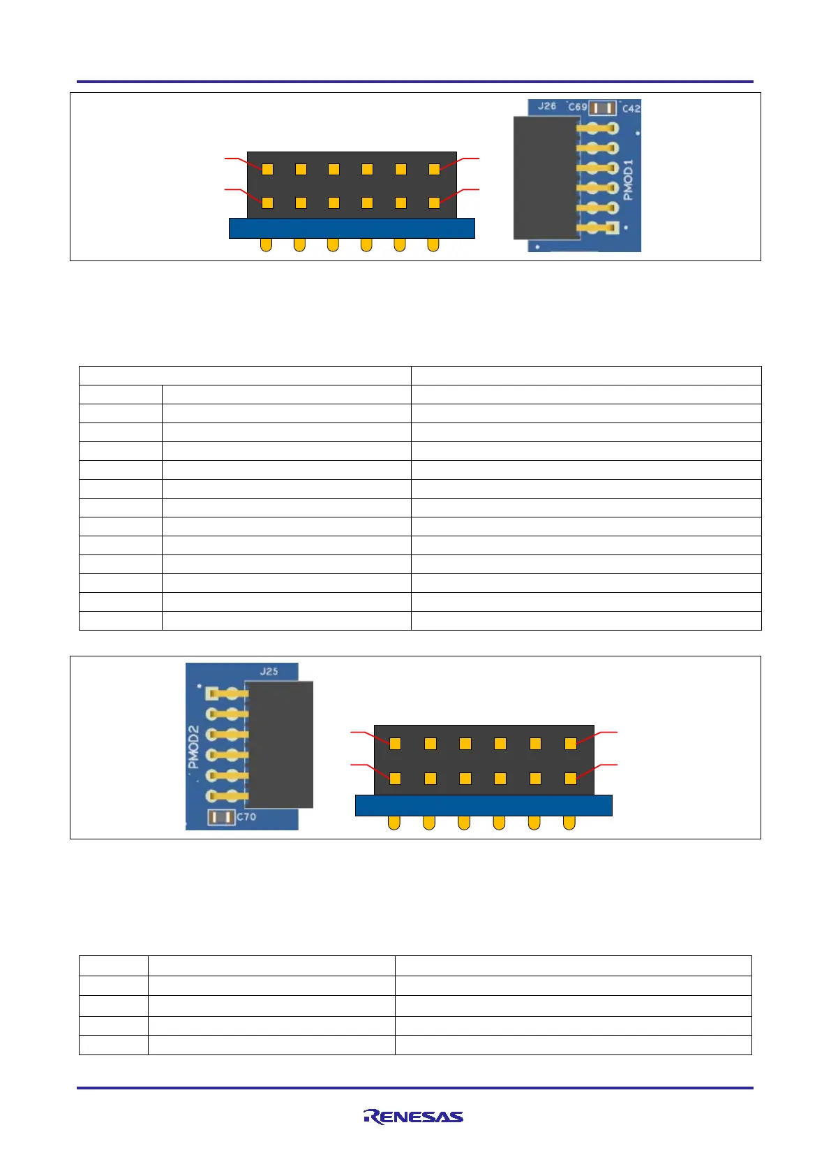
Figure 11. Pmod 1
5.3.3.2 Pmod 2
A 12-pin Pmod connector is provided at J25, Pmod 2.
Table 14. Pmod 2 Connector
GPIO / INT (slave to master)
GPIO / RESET (master to slave)
Figure 12. Pmod 2
5.3.4 Arduino™ Connector
Near the center of the System Control and Ecosystem Access area is an Arduino Uno R3 compatible
connector interface.
Table 15. Arduino Uno Connections
Arduino Compatible Connector

 Loading...


