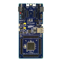
Renesas RA Family EK-RA6M5 v1 – User's Manual
R20UT4829EG0100 Rev. 1.00 Page 2 of 34
Mar.15.21
6.1 Ethernet ................................................................................................................................................. 26
6.2 USB High Speed ................................................................................................................................... 27
6.3 Quad-SPI Flash ..................................................................................................................................... 28
6.4 Octo-SPI Flash ...................................................................................................................................... 28
6.5 CAN Bus ................................................................................................................................................ 29
7. MCU Native Pin Access Area ................................................................................................ 30
7.1 Breakout Pin Headers ........................................................................................................................... 30
7.2 MCU and USB Current Measurement ................................................................................................... 31
8. Certifications .......................................................................................................................... 32
8.1 EMC/EMI Standards .............................................................................................................................. 32
8.2 Material Selection, Waste, Recycling and Disposal Standards ............................................................ 32
8.3 Safety Standards ................................................................................................................................... 32
9. Design and Manufacturing Information .................................................................................. 33
10. Website and Support ............................................................................................................. 33
Revision History ............................................................................................................................ 34
Figures
Figure 1. EK-RA6M5 Board Top Side ............................................................................................................. 5
Figure 2. EK-RA6M5 Board Bottom Side ........................................................................................................ 6
Figure 3. EK-RA6M5 Kit Contents .................................................................................................................... 8
Figure 4. EK-RA6M5 Board Functional Area Definitions ............................................................................... 10
Figure 5. EK-RA6M5 Board Block Diagram .................................................................................................. 11
Figure 6. Copper Jumpers ............................................................................................................................. 12
Figure 7. System Control and Ecosystem Access Area ................................................................................ 14
Figure 8. Power Supply Options .................................................................................................................... 15
Figure 9. EK-RA6M5 Debug Interface ........................................................................................................... 17
Figure 10. Seeed Grove and SparkFun
®
Qwiic Connectors .......................................................................... 19
Figure 11. Pmod 1 ......................................................................................................................................... 21
Figure 12. Pmod 2 ......................................................................................................................................... 21
Figure 13. Arduino Uno Connectors .............................................................................................................. 22
Figure 14. mikroBUS Connection .................................................................................................................. 23
Figure 15. USB Full Speed Connector .......................................................................................................... 24
Figure 16. User LEDs .................................................................................................................................... 25
Figure 17. Power LED ................................................................................................................................... 25
Figure 18. Reset and User Switches ............................................................................................................. 25
Figure 19. Boot Mode .................................................................................................................................... 26
Figure 20. Special Feature Access Area ....................................................................................................... 26

 Loading...