EasyManua.ls Logo

Renesas RH850/D1x - Test Pin Connectors

Renesas RH850/D1x
37 pages
To Next Page IconTo Next Page
To Previous Page IconTo Previous Page
Loading...
D1M1A Mango Adapter Board Manual
23
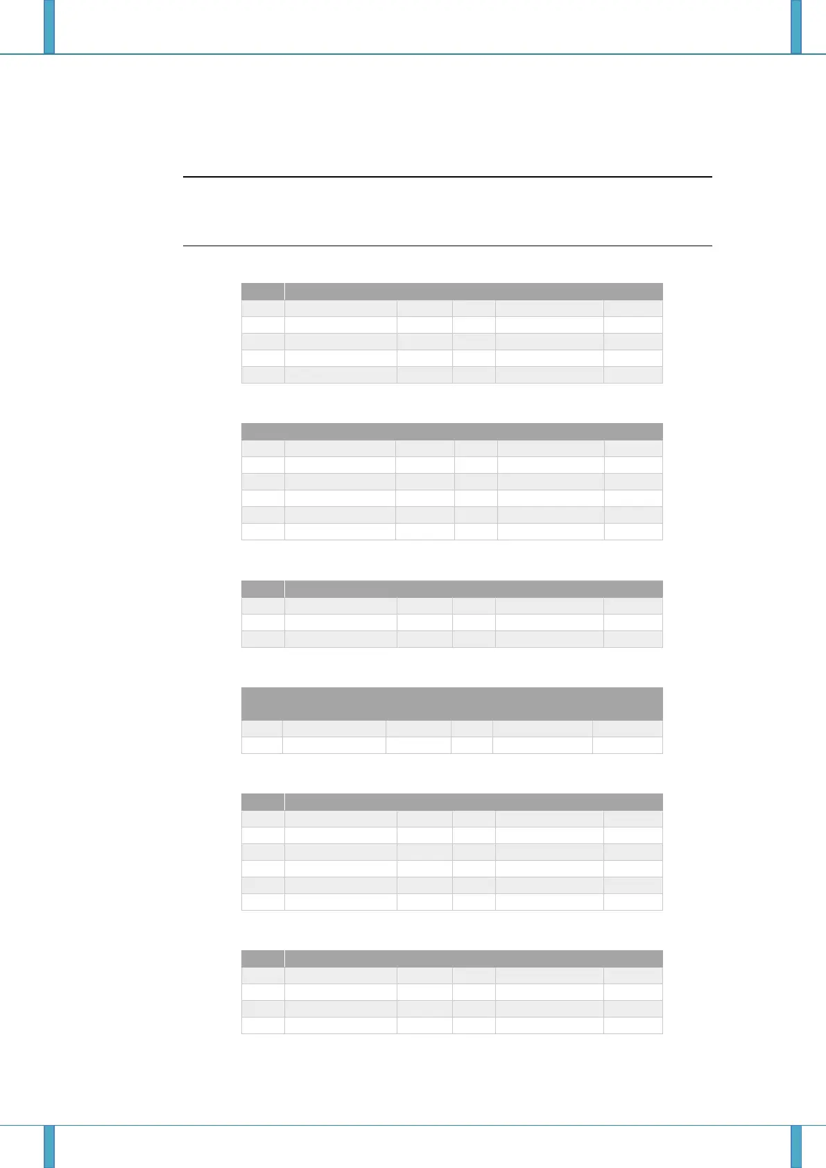
8.2 Test pin connectors
Note: The test-pin headers CN3 to CN12 are directly connected to the MCU pins,
therefore special care must be taken to avoid any electrostatic discharge or
other damage to the device.
Table 8-3: Pin assignment of connector (CN3) P0
Pin
Power Domain
Port
Pin
Power Domain
Port
1
EVCC
P0_0
2
EVCC
P0_1
3
EVCC
P0_2
4
EVCC
P0_3
5
EVCC
P0_4
6
EVCC
P0_5
7
EVCC
P0_6
8
EVCC
P0_7
9
EVCC
P0_8
10
EVCC
P0_9
Table 8-4: Pin assignment of connector (CN4) P10
Pin
Power Domain
Port
Pin
Power Domain
Port
1
A0VCC
P10_0
2
A0VCC
P10_1
3
A0VCC
P10_2
4
A0VCC
P10_3
5
A0VCC
P10_4
6
A0VCC
P10_5
7
A0VCC
P10_6
8
A0VCC
P10_7
9
A0VCC
P10_8
10
A0VCC
P10_9
11
A0VCC
P10_10
12
A0VCC
P10_11
Table 8-5: Pin assignment of connector (CN5) JP0
Pin
Power Domain
Port
Pin
Power Domain
Port
1
EVCC
JP0_0
2
EVCC
JP0_1
3
EVCC
JP0_2
4
EVCC
JP0_3
5
EVCC
JP0_4
6
EVCC
JP0_5
Table 8-6: Pin assignment of connector (CN6) System Function Pins
Pin
Power
Domain
Port
Pin
Power
Domain
Port
1
EVCC
FLMD0
2
EVCC
PWRCTL
3
EVCC
PWRGD
4
EVCC
RESETZ
Table 8-7: Pin assignment of connector (CN7) P1
Pin
Power Domain
Port
Pin
Power Domain
Port
1
B0VCC
P1_0
2
B0VCC
P1_1
3
B0VCC
P1_2
4
B0VCC
P1_3
5
B0VCC
P1_4
6
B0VCC
P1_5
7
8
9
10
11
12
Table 8-8: Pin assignment of connector (CN8) P11 / Analog Pins
Pin
Power Domain
Port
Pin
Power Domain
Port
1
A0VCC
P11_0
2
A0VCC
P11_1
3
A0VCC
P11_2
4
A0VCC
P11_3
5
6
7
8

Other manuals for Renesas RH850/D1x

Related product manuals