D1M1A Mango Adapter Board Manual
【DRAFT VERSION - CONFIDENTIAL】
8
3 Power supply
3.1 Power supply structure
3.1.1 Current Measurement Jumpers
Each power supply of the MCU is routed through a single Jumper before connecting it to the MCU. This makes
it possible to measure the current consumption of the MCU for each power supply domain in separate.
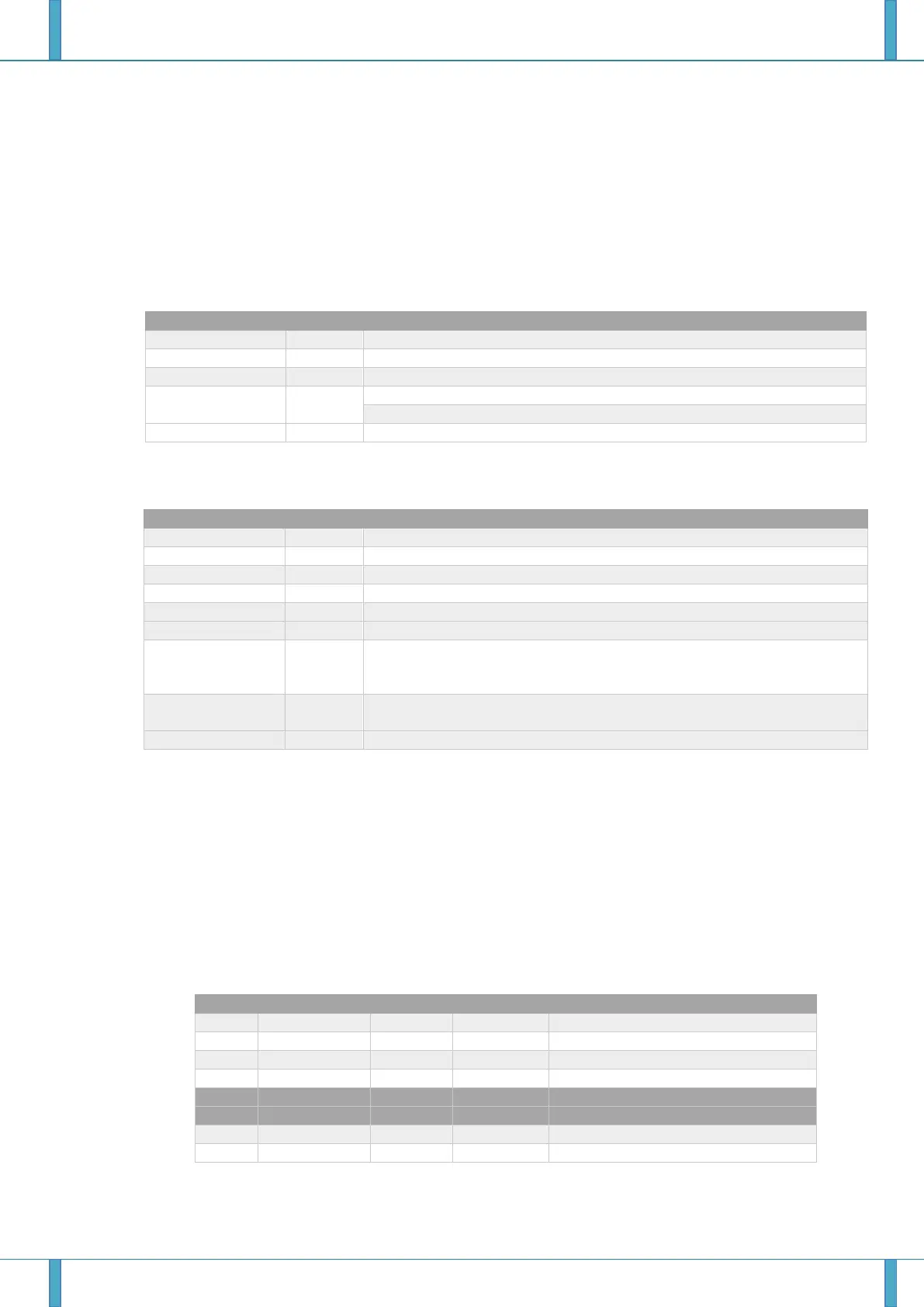
Table 3-1: Current measurement jumpers (excluding I/O ports supply)
AWO digital circuits via on-chip voltage regulator; nominal 3.3 V and 5 V
MainOsc and SubOsc; nominal 3.3 V and 5 V
Flash memory and PLL circuits; nominal 3.3 V
Zero point detection circuit; nominal 5 V
Reference voltage of Zero Point detection, normal 5V
Reference voltage of A/D Converter, normal 3.3V and 5V
Table 3-2: Current measurement jumpres for I/O port supply
Port buffers P0 and JP0; nominal 3.3 V and 5 V
Port buffers port group P1; nominal 3.3 V and 5 V
Port buffers port group P3; nominal 3.3 V and 5 V
Port buffers port group P42; nominal 3.3 V and 5 V
Port buffers port groups P43_0, P43_1, P44 and P45; nominal 3.3 V and 5V.
Port buffers port group P21 (Serial Flash); nominal 3.3 V.
Port buffers port groups P16 and P17 (Stepper Motor Controller/Driver) ;
• nominal 5 V when used for stepper motor operation
• nominal 3.3 V and 5 V when not used for stepper motor operation
Ports buffers port groups P10 and P11 (A/D Converter analog circuits and
input buffers); nominal 3.3 V and 5 V
SDR-SDRAM I/F port buffers; norminal 3.3 V.
Notes on current measurement:
Currently, the reset line is not pulled-up to full EVCC voltage. This is caused by the drop out voltage of LED24
“RESET ACT” (V
RESET
is only ~3.7V when EVCC is 5V). This leads to an EVCC leakage current caused by the
RESETZ input buffer. To correctly measure the EVCC current, please add a 6.2kΩ resistor in parallel to LED24
“RESET ACT” on the Mango Main Board.
3.1.2 Voltage regulators and DC-DC converters
The power domains on the adapter board are supplied by the main board. The following voltages are generated
on the main board.
Table 3-3: Main Power supply Source IC output voltage (from Main board)
 Loading...


