D1M2H Mango Adapter Board Manual
14
6 Multiplex Control
6.1 Overview
Multiplexers (mainly for Video I/O and Ethernet) shall be manually controlled by the user themselves via DIP
switches (DSW1 and DSW2). Thus the user has responsibility to avoid misconfiguration of the multiplexers that
might destroy the device.
The following multiplexers are placed onto the adapter board. This has been done for all high-speed I/O signals
in order to avoid unnecessary routing on the main board and for signals that are directly used on the adapter
board. For the RSDS-Interface, the connector is placed onto the adapter board, all other signals will be routed to
the main board, independent from the switch position.
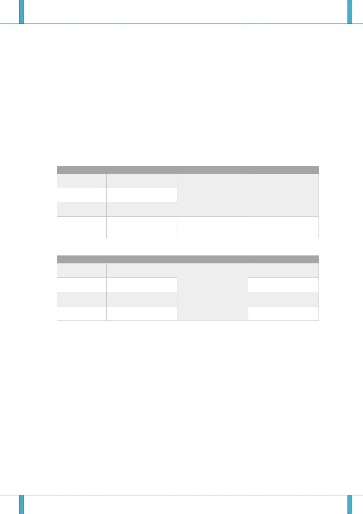
Table 6-1: Signal Assignment and function of DSW1
Adapter Board Encoding
Address (ABEA) 2
Adapter Board Encoding
Address 1
Adapter Board Encoding
Address 0
Connect P47_6 and
P47_7 Pins to Video /
GPIO Blocks
Connect P47_6 and
P47_7 Pins to Ethernet
Blocks
Table 6-2: Signal Assignment and function of DSW2
Connect MCU Pins to
Video / GPIO Blocks
Connect MCU Pins to
RSDS Connector
Connect MCU Pins to ITU
Connector
Connect MCU Pins to
Ethernet 1 Connector
Connect MCU Pins to
Ethernet 0 Connector
 Loading...


