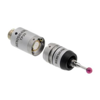
Storing and changing probe modules
NOTES: The inhibit switch in the inhibit version of the TP20 body will be automatically actuated by the magnetic field when it
approaches the front of the MCR20 probe module changing rack. The minimum distance from the MCR20 probe module changing
rack at which the TP20 is armed will vary with height.
When using long styli fitted to the EM1 STD or EM2 STD probe modules, do not store them in ports three or four of the MCR20 or
MSR1 rack.
Calculating the safe clearance position
The recommended safe clearance position is located at the minimum distance from the port centre (at docking height Z) where the probe will
be armed, if the probe module is attached.
The safe clearance position for any port (n) can be calculated from:
{Xn, Ys, Z} where Ys = Y – 100 mm