Do you have a question about the Renishaw TS20 and is the answer not in the manual?
Details warranty terms and conditions for Renishaw equipment.
Emphasizes safe operation by trained personnel according to manufacturer instructions.
Advises keeping system components clean and treating the probe as a precision tool.
States that patents are not applicable for this product.
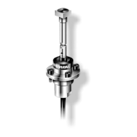
Defines the TS20 as a hardwired 2-axis touch-trigger probe for tool setting on CNC lathes.
Recommends eye protection in applications involving machine tools or CMMs.
Outlines the supplier's responsibility to inform users about hazards and provide safety guards.
Details guidelines for installers to ensure compliance with regulatory requirements.
Warns that improper operation may impair the equipment's provided protection.
Introduces the TS20 as a 2D touch-trigger probe for CNC lathe tool setting.
Explains the need for a signal conditioning module or interface unit for probe signal processing.
Describes probe mounting with specific interface units for signal processing.
Details the specifications and routing recommendations for the TS20 probe cable.
Highlights critical safety precautions and requirements for competent installation personnel.
Advises routing the probe cable away from high-current cables to prevent interference.
Addresses potential false triggers and suggests investigating power supply interference.
Recommends mounting interface units away from potential sources of electrical noise.
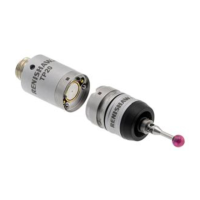
Discusses stylus fitting, including break stems and replacement procedures.
Notes that stylus squareness specification is not guaranteed after replacing a straight stylus.
States that stylus squareness and parallelism are not guaranteed after replacing a cranked stylus.
Mentions availability of toolsetting software routines for various machine controllers.
Details specifications like sense directions, repeatability, and temperature limits for the straight stylus probe.
Provides specifications for the cranked stylus, noting reduced repeatability performance.
Specifies the maximum allowed overtravel distances for different directions to prevent probe damage.
Shows dimensional details and mounting recommendations for the probe with an SCM.
Guides on how to fit and replace stylus tips and break stems, including torque specifications.
Explains how to align the stylus with the machine axes by adjusting clamping screws.
Provides dimensional information for the signal conditioning module.
Details dimensions and mounting of the TS20 probe with an SCM.
Lists electrical specifications for the TS20 probe with SCM, including load resistor and voltage ratings.
Describes the probe's requirement for a load resistor and provides electrical ratings.
Details the probe cable's construction and circuit wiring.
Presents electrical performance data, including standby current and voltage drops.
Illustrates and quantifies typical output voltage performance under specific load and supply conditions.
| Brand | Renishaw |
|---|---|
| Model | TS20 |
| Category | Industrial Equipment |
| Language | English |