3-7
www.renishaw.com/ts20
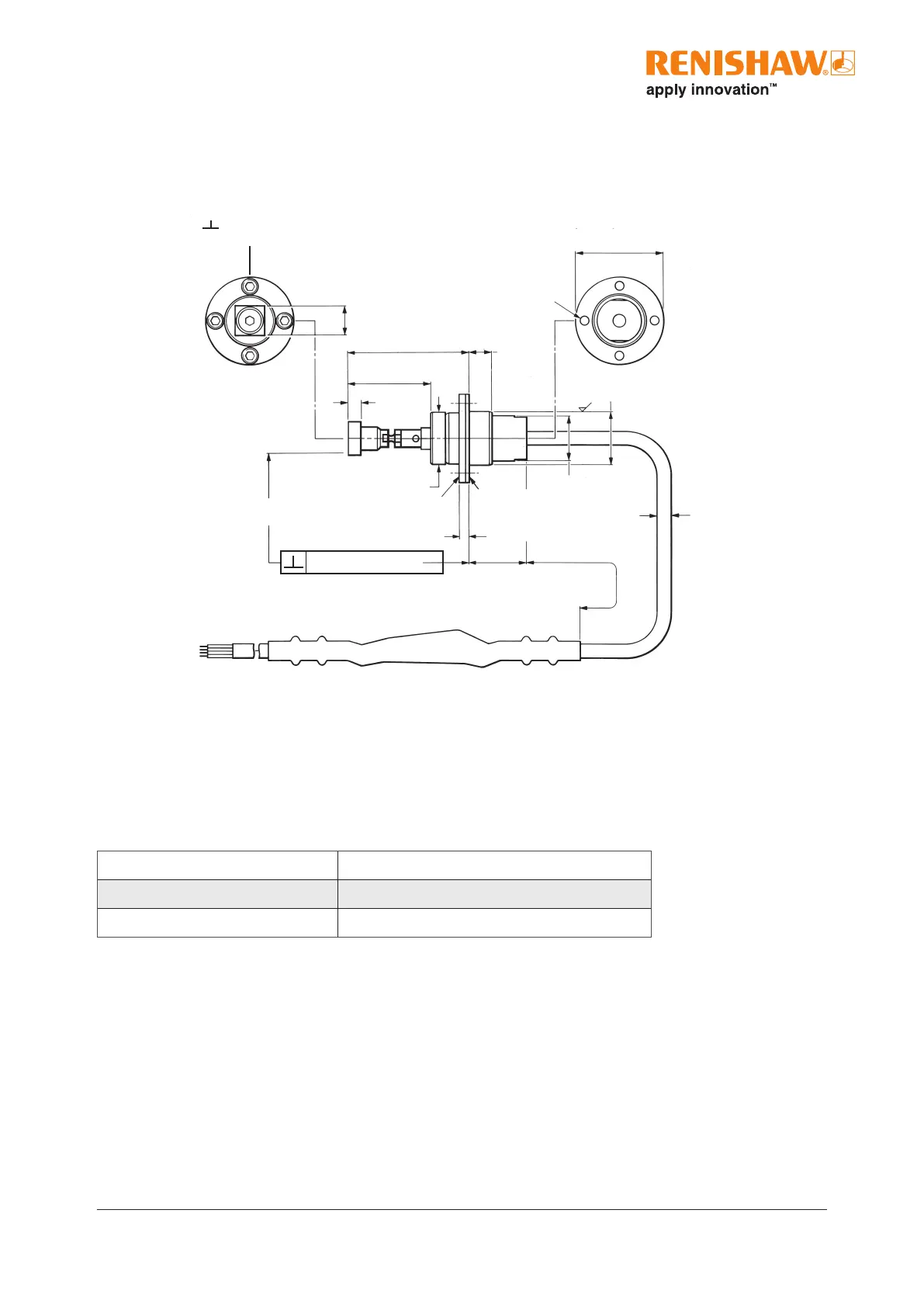
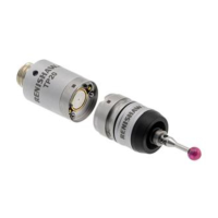
TS20 probe with signal conditioning module
Dimensions mm (in)
10 (0.39) square
Straight or cranked styli
Ø29.5
(Ø1.16)
7.9 (0.31)
7.35 (0.29)
A - see page 3-2
B - see page 3-2
4 (0.16)
0.8µm
(32µin)
Ø
14.95 (0.589)
14.85 (0.585)
Ø4.4 MAX
(Ø0.173 MAX)
295
(11.6)
20.7 (0.82)
19.3 (0.76)
0.02 mm (0.00079 in)
3.1 (0.12)
Clamping ring
Clamps the probe in its desired position
Ø17.4 (Ø0.69)
Four tip faces mutually
or // to 6µm
(0.00024in)
Ø
Spacer
Provides a secure seating
face when installing the probe.
Four holes
Ø3.3(Ø0.13).
Equi-spaced
on Ø23.5
PC(0.925)
17.85 (0.703)
17.75 (0.699)
Electrical specication
TS20 with signal conditioning module (SCM)
The TS20 probe is designed to be used wIth a load resistor.
Minimum load resistor at 30V 1K2 Ohms
Maximum supply voltage 30V Maximum current 25mA - probe seated
Minimum supply voltage 9V Minimum current 2mA - probe seated
Cable
Four core 7/0,2 polyurethane insulated and screened cable.
Probe circuit - red and blue cores, (yellow and green are not used).
The load resistor is connected in either positive or negative lead. For more information, see page 3-8,
“Typical performance with 4K7 load resistor and 24V supply”.
It can be any value that does not cause the circuit to exceed the max/min current ratings.
The probe is protected against reverse voltage within the specied ratings.