31
Wiring
IN1
+ -
IN2
CAN/RS485
TYPE-C
OUT1 OUT2 IN3 OUT3
OUT
+
DC load
(≤30V DC, ≤5A)
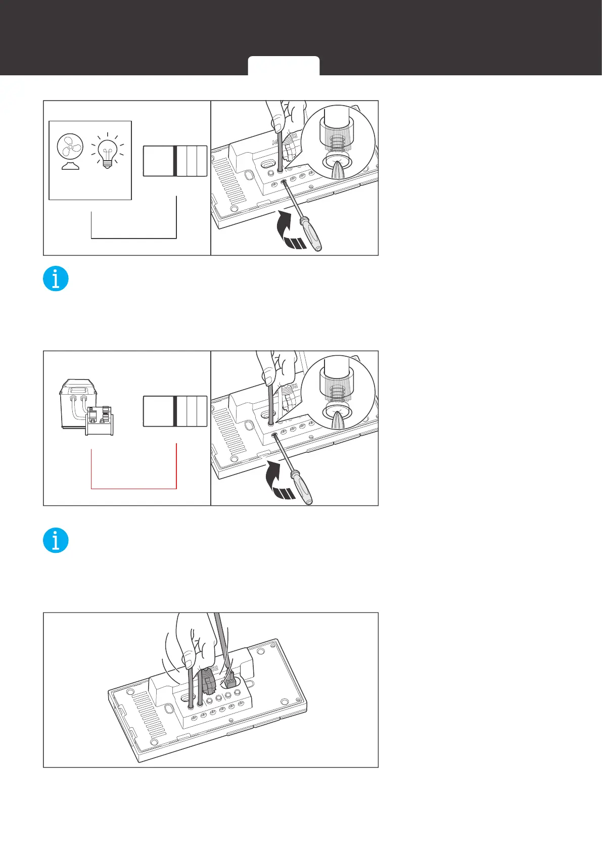
3. Insert the reserved adapter
cable connecting to the
positive terminal of the
load into the Renogy ONE
output terminal (OUT), and
use a Phillips screwdriver
to turn the wire hatch
screw clockwise.
NOT
z
Strip some insulation off the bare wire end according to the depth of the installation hole.
z
The maximum screw torque of wire hatch is 0.4 N•m. Do not overtighten the screws to avoid
damage to the hatch.
IN1
+ -
IN2
CAN/RS485
TYPE-C
OUT1 OUT2 IN3 OUT3
IN
+
4. Insert the adapter cable
connecting to the positive
end of the DC power
supply into the Renogy
ONE input terminal (IN),
and use a screwdriver to
turn the wire hatch screw
clockwise.
NOT
z
Strip some insulation off the bare wire end according to the depth of the installation hole.
z
The maximum screw torque of wire hatch is 0.4 N•m. Do not overtighten the screws to avoid
damage to the hatch.
IN1
+ -
IN2
CAN/RS485
TYPE-C
OUT1 OUT2 IN3 OUT3
5. Make sure all connections
are tight and secure.
12V Power Cable Communication Cables External Load
 Loading...