7.0 Controls
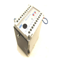
7.1 Analogue Units
Potentiometers and link switches are used for adjusting throughput configuring analogue units to operate
with specific feeders. The functions and locations of the potentiometers and link switches are fully explained
in the operating instruction manual for the controller.
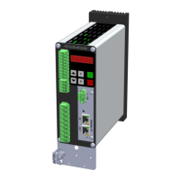
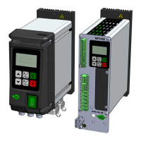
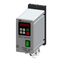
7.2 Digital units
Digital units are provided with a display and programming keys that are used for adjusting all parameters and
the feeder throughput. Because the same keys and display are used for all different settings, a strict setting
up procedure must be followed. Pass code protection of the parameter settings prevents tampering by un-
authorized personnel.
Factory settings can be recalled for setting up as from new or when a control unit is used with another
feeder, for instance. The factory settings are reinstated by selecting menu “C 210“(Parameter “FAC“). Under
the same menu it is possible to recall user settings that have been previously stored using Code
“C143“(Parameter “US.PA“).
Below is an explanation of the main setting components that are provided on controllers.
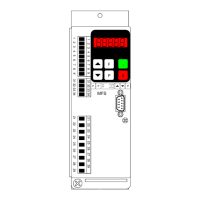
7.2.1 Three key control panel
The operation and setting up of the unit is achieved by using three keys in conjunction with an LED display
that can be found on the front panel. These controls are all that is needed for selecting all operating modes
and setting all parameters.
To prevent accidental or unauthorized adjustment the parameter settings are stored under user menus. A
pass code must be entered to open the menus. Different menu codes are provided for the various function
groups (refer to controller operating instructions).
LED-Display
Increase Decrease Enter
Pushing down the key for a short time causes the display to increase, or decrease, by one step (unit or
tenth). Depressing the key for a longer time causes the displayed value to step in ten units at a time.
Changed values are saved upon leaving the programming mode or if no keys are pressed for a pe-
riod of 60 seconds.
All setting routines are commenced by pressing the programming button “P“. The following diagram should
clarify the sequence in which keys are pressed:
11
 Loading...