EasyManua.ls Logo

REO REOVIB MFS 368 User Manual

REO REOVIB MFS 368
32 pages
To Next Page IconTo Next Page
Page #1 background imageLoading...
Page #1 background image
MFS368_ANL_rev01.en.doc
18.08.2023
REOVIB
Control units for vibratory conveyor technology
MFS 368
Frequency converter for vibratory feeders
Question and Answer IconNeed help?

Do you have a question about the REO REOVIB MFS 368 and is the answer not in the manual?

REO REOVIB MFS 368 Specifications

General IconGeneral
BrandREO
ModelREOVIB MFS 368
CategoryIndustrial Equipment
LanguageEnglish

Summary

Safety Instructions

General Safety Instructions

General instructions for the personal safety of operating staff and product safety.

Intended Use and Declarations

Intended Use

Describes that the units are electrical equipment for industrial plants for controlling vibratory feeders.

Declaration of Conformity

States that the products conform to specified EU guidelines and standards.

1.0 General Information

Special Features of the REOVIB MFS 368

Lists key features such as output voltage, adjustable frequency, and special control modes.

2.0 Functionality

Controller Operation Modes

Explains how the controller generates adjustable output voltage and frequency for feeders.

2.1 Track Control

2.2 Operation with Two Speeds

2.3 Control Inputs and Outputs

Input and Output Signal Details

Details enable input, sensor input, external setpoint, and various control outputs.

2.4 Touch Panel Operation

Display Symbols and Key Functions

Explains operating display symbols, status line symbols, and key functions.

3.0 Unit Structure

IP54 and IP20 Housing Versions

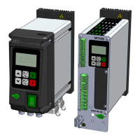
Describes the features and connections of the IP54 and IP20 housing versions.

4.0 Technical Data

Technical Specifications

Load Supply, Terminals, and Current Consumption

Covers load requirements, terminal details, and unit current consumption.

Warning Signs and Environmental Conditions

Highlights warning signs and specifies conditions like temperature and coolant.

5.0 Ordering Code

Interface and Control Connection Options

Details available interfaces and internal control connection options.

6.0 Possible Settings

Feeder, Frequency, and Auto-Freq Settings

Covers settings for feed rate, setpoint, frequency, and auto-frequency search.

Limit Values and Interface Settings

Parameters for limiting values and configuring interface/protocol settings.

6.1 Information and Service

Service Menu Functions

Access to service functions like error reset, factory settings, and parameter saving.

7.0 Operating Elements

Setting Behaviour and Shortcut Menu

Explains menu navigation, parameter adjustment, and shortcut menu usage.

7.1.1 Parameter Setting Example

7.1.2 External Setpoint Example

8.0 Commissioning

Preparatory Measures and Coil Frequency

Checks before commissioning, coil frequency considerations, and measurement guidance.

9.0 Controller Settings

Controller Mode and Accelerometer Mounting

Notes on controller mode, accelerometer requirements, and mounting instructions.

9.3 Acceleration and Vibration Amplitude

9.4 Determining Resonant Frequency

Manual Vibration Frequency Setting

Procedure for setting frequency manually without an accelerometer to find the resonant frequency.

9.5 Commissioning in Control Mode

Automatic Frequency Search Procedure

Step-by-step guide for initial commissioning using automatic frequency search.

10.0 Troubleshooting

Error Messages and Problem Solutions

Lists common error messages, their causes, and troubleshooting steps.

11.0 Housing Version Connection

Connection Diagrams for Housing Versions

Illustrates internal and external connections for IP54 and PV versions.

12.0 Control Cabinet Connection

External Enable and Setpoint Connections

Wiring Options for Enable and Setpoint

Shows different wiring configurations for external enable and setpoint inputs.

13.0 Dimension Drawing

Unit Dimensions and Sizes

Provides dimensional drawings and size specifications for different unit versions.

Control Cabinet Installation Clearances

14.0 Assembly Instruction

A 1.0 Accessories / Options