REOVIB MFS 368
Operating instructions
24
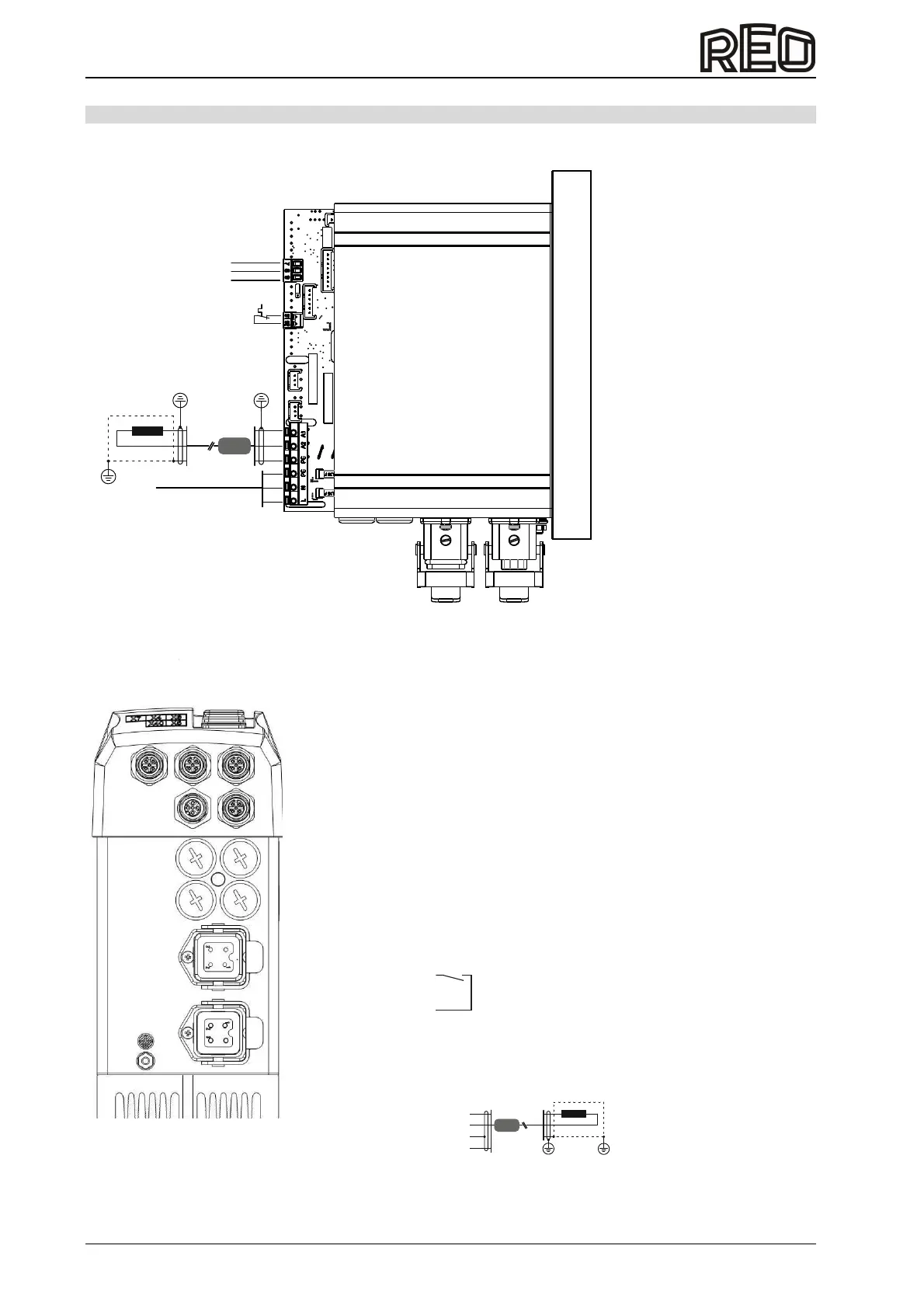
11.0 Housing version connection
Internal connection 3...8 A units
L,N,PE / 50/60Hz
N
PE
PE
A2
A1
L
Thermal switch
connection (Series)
Ferrite sleeve
GND
Input
+10V/DC
External setpoint
{
Different connection options are available depending on the unit design.
Plug and Vib (PV) version:
X1
X0
X40 X5
X7
X4 X6
1 =
= 2 nc
3 = GND
= 4
5 = OutputTime out +24V
1 = A1
2 = A2
3 = Shield
4 = PE
X4 Track control sensor
X40 Acceleration sensor
X6 Enable input
X5 Status output
X1 Output feeder
X0 Mains connection
110 / 230 V,
50/60 Hz
1 = L
2 = N
3 = nc
4 = PE
1 = +24 VDC
2 = nc
3 = GND
4 = +24VDC Input
1 = +24 VDC
2 = Input
3 = GND
4 = nc
1 = +24 VDC
2 = nc
3 = GND
4 = +24 VDC Input
Rela onta ty c c (Max. 24V, 1A)
Ferrite sleeve
X7 Output 24V Valve
1 = +24 VDC Output
3 = GND
To comply with EMC regulations, a shielded output cable must be installed to the feeder, which must also
be routed through supplied the ferrite sleeve.
 Loading...