REOVIB MFS 368
Operating instructions
7
1.0 General
The control unit generates an adjustable output frequency for the vibratory feeder independently of the
mains frequency. The PFC circuit on the input side ensures a constant output voltage both at an input
voltage of 110 V and 230 V.
Mains voltage fluctuations have no influence on the feed rate. In addition, the operating mode “Amplitude
control" combined with an accelerometer enables a constant feed rate even with changing feeder loads.
In this operating mode, the feeder's resonant frequency can also be determined and the output frequency
for the feeder continuously tracked.
An integrated track control enables a backlog circuit to be set up for material control via a PNP distance
sensor.
For the operation of a blowing air valve, a 24 VDC output is available in the IP54 housing version.
The unit is operated via an LC display and programming buttons. All the settings can be done using this
display without opening the housing.
Special features:
• Output voltage up to 205 VAC, independent of
mains supply.
• Mains frequency independent, adjustable
output frequency
• Min and max limits of the frequency range
adjustable
• Adjustable current limit for maximum coil
current
• Constant feed rate in the event of mains
fluctuations
• Control of the resonant frequency
• Status relay On / Off
• Ready relay (IP20 only)
• Track control
• 24 VDC Output for e.g. air valve (IP54 only)
• Four application-specific parameter sets can
be stored
• With option "Interface operation via field bus"
• Thermal switch input for coil temperature
monitoring
2.0 Function
The controller generates an adjustable output voltage with an adjustable output frequency that is
independent of the mains supply. The input-side PFC circuit ensures a constant output voltage at an input
voltage of 99 V to 264 V. The output voltage is changed to control the feed rate. The output can be
switched on or off via the keyboard or an enable input by a higher-level external control unit. After
switching on the unit, the output is ramped up over an adjustable time ramp (soft start) or ramped down
after switching off (soft stop). The unit can be operated in a manual mode at constant output frequency or
in controller mode with amplitude control and frequency control. For controller mode an acceleration
sensor e.g. SW10 is required, which is mounted on the vibrating part of the feeder. This sensor detects
the feeder's vibration movement and reports this actual value back to the internal controller. In this
operating mode, in addition to the amplitude control, the feeder's resonant frequency is determined and
adjusted accordingly with different loads, so that a constant flow of parts results with an optimum vibrating
frequency of the feeder. The setpoint for the feed rate is specified as standard via the internal display but
can also be supplied externally by means of a 0...10 V or 0/4...20 mA DC signal. For feed rate control, an
integrated track control allows the realisation of a material flow control. This function requires an external
24 V PNP distance sensor to detect the conveyed parts. This creates a defined material flow via
adjustable time stages for switch-on and switch-off delay. The "time out" function can be used to monitor
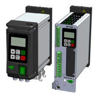
Control cabinet version
 Loading...