REOVIB MFS 368
Operating instructions
25
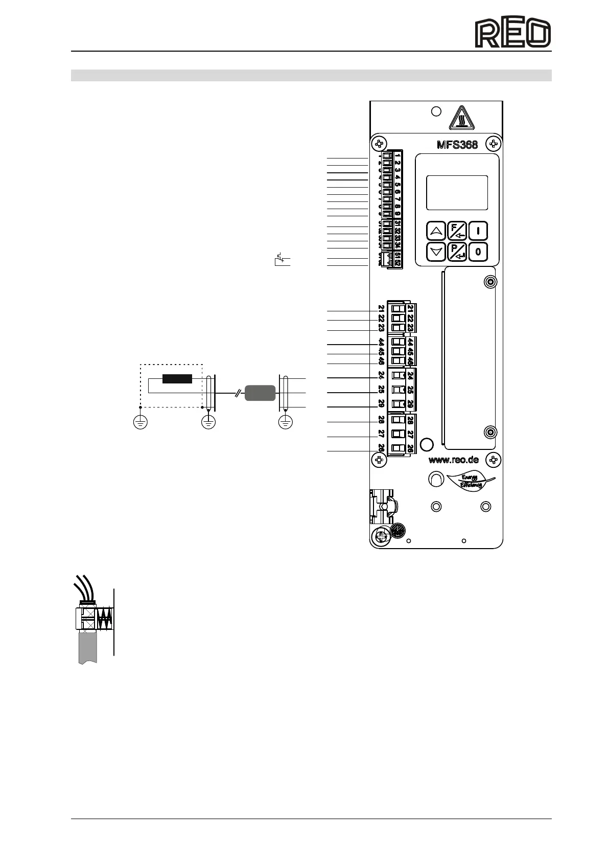
12.0 Connection of control cabinet version
37383635
GND
Input
+24V/DC
GND
Input
+24V/DC
GND
Input
+10V/DC
(Black) GND
(Orange) Input
(Red) +24V/DC
Shielding
A1
A2
PE
PE
L
N
NC
CO
NO
NC
CO
NO
Input
+24V/DC
Trackcontrol sensor
Enable
External setpoint
ACC-Sensor
Thermal switch connection
(Series)
Status relay
Ready relay
Mains connection
{
{
{
{
Ferrite sleeve
Magnet connection
To comply with EMC regulations, a shielded output cable must be installed to the feeder, which must also
be routed through supplied the ferrite sleeve.
EMC shield clamp (accessory)
Order No.: 27100190100
Spring clamp for the shield connection for
the output cable and the
acceleration sensor

 Loading...