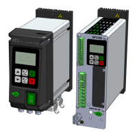
REOVIB MFS 368
Operating instructions
18
8.0 Commissioning
8.1 Preparatory measures
Notes
With the control units described here, it is possible to adjust the resonant frequency of
the connected feeder. Since in this case even a small setpoint value can lead to full
operation of the feeder, appropriate care must be taken to ensure that no damage
occurs in the feeder due to coil hammering.
In practice, however, the resonant frequency range cannot be used without feedback of
the acceleration, as the feeder would not be loadable or controllable. Therefore, a certain frequency offset
from the resonant frequency must be set. The frequency offset can be both below and above the
resonant frequency.
Independent of the input voltage, the frequency converter's output voltage is 205 VAC
when delivered. When using 110V VAC coils, the output voltage must be set using
parameter: "Umax", otherwise the feeder coil and the drive or the vibratory feeder may
be damaged.
• Check whether the local supply voltage corresponds to that of the unit (type plate information) and
whether the connected power of the feeder is within the permissible power range.
• Check that the output voltage and frequency of the control unit are compatible with the selected
magnet.
• Connect the control unit according to the enclosed connection diagram
• Adjust setpoint to zero
• Switch off Enable (if used)
The control unit is now basically ready for operation and can be switched on (mains, Enable).
Resonance frequencies: Due to the structure of the spring-mass system of the feeders, the system can
resonate at several vibrating frequencies. The additional resonant points are at a multiple of the desired
frequency. In critical cases, the automatic frequency search cannot reliably detect the desired vibrating
frequency; in this case, the frequency may have to be adjusted manually.
Storage: After a storage period of one year, the internal DC link capacitors must be reformed. To do this,
connect the MFS to the supply voltage for 60 minutes without load; for the IP54 version, also switch on
the mains switch. If the product is stored for more than one year, the manufacturer must take care of the
reforming. Failure to observe the reforming prescriptions may result in the destruction of the unit.
8.2 Operating frequency of the feeder coils
When using the unit for the first time the current in the solenoid circuit should be
checked with an RMS meter or the heat development at the coil should be monitored,
as the current through the coil may increase at low frequency settings.
In order to avoid excessive power consumption and thus possibly an overload of the coils, please make
sure that the coils are designed for the operating frequency.
An incorrect vibrating frequency may lead to the destruction of the coils and the drive or the vibratory
feeder. Make sure that suitable feeder coils are used for the desired vibrating frequency.
8.3 Measurement of output voltage and output current
Since the unit output is an electronic frequency converter with pulse-width modulated switching signals,
the voltage and current values cannot be measured with any standard measuring device. Moving iron
meters are recommended for measuring these values.
!
!
!

 Loading...