REOVIB MFS 368
Operating instructions
11
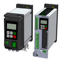
3.0 Structure
The unit is available as IP54 or IP 20 version.
3.1 IP54
• Power switch
• Control and display panel
• Mains supply lead (optional)
• Output cable or output socket for feeder connection
• Sensor sockets. 24 VDC sensors with PNP output are provided.
3.2 IP20
Fixing points for attachment to a mounting plate.
Electrical connection on external terminals.
4.0 Technical data
Protection type IP54 IP20
Protection class I
Supply voltage 99…264 VAC
Max. permissible input current*
1
(Important information in Chapter 4.5)
I
n
: 2 A
Input frequency 50 / 60 Hz
Inrush current Î= 9 A, 20 ms
Power loss max. 55 W
Output voltage 0... 205 V +/- 5%
Output current 3 / 6 / 8 A +/- 5%
Output frequency*
2
20…140 Hz
Recommended automatic circuit
breaker
6 A B/C
RCD Type "B".
Mains system
TN system
Rated short-time withstand current
(I
cw
)
<10 kA
Rated short-circuit current (I
cc
) <10 kA
Enable input Contact / 24 VDC
Analogue setpoint 0...+10 VDC, 0/4…20 mA
Air valve output 24 V, 100 mA, DC -/-
Timeout output
Backlog sensor 24 V, PNP (100 mA, DC)
Status relay (On/Off)*
3
Make contact (24 V, 1 A)
Changeover
1 A)
Ready relay (fault) -/-
Operating temperature 0...+40 °C
Storage temperature -10...+65 °C
Rel. humidity (storage) 10...95 % RH without condensate
Weight approx. 2.7 kg approx. 2.3 kg
*
1
Important information in Chapter 4.5 "Current consumption".
Non-observance can lead to malfunction and failure.
*
2
Other frequencies on request.
*
3
The connections of status and ready relays cl. 21-23 and cl. 44-46 must not be combined with
different mains classes. Both relay contacts may only be used with signals of the same mains
class.
 Loading...