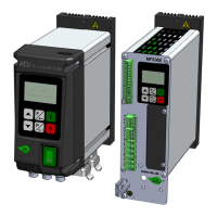
REOVIB MFS 368
Operating instructions
19
9.0 Settings
9.1 Notes on controller mode
• For controller mode, an accelerometer mounted on the vibratory feeder is required, e.g. SW 70 (for
IP54 units) or SW10 (for IP20 units).
• In control mode with sensor feedback, all vibrations detected by the sensor are processed in the
control circuit. External vibrations caused by neighbouring machines, by an unstable position of the
feeder, or by unstable mounting of the accelerometer can lead to erroneous control performance.
Especially during the AFS automatic frequency search, no external influences must be allowed to
affect the feeder.
9.2 Mounting the accelerometer
The accelerometer must return the movement and the acceleration of the feeder to the control circuit of
the control unit. It is therefore very important that no additional spurious vibrations caused by an
unfavourable sensor mounting are measured.
The sensor should be mounted in the direction of
vibration (ideally at the same inclination as the
feeder springs) on a solid mounting block which
does not generate any natural vibrations.
The accelerometer cable must be supported with a cable clamp to prevent the cable
from being damaged.
In control mode, the output signal level directly determines the feeder's maximum vibration
amplitude.
!
SW SW
Cable clamp

 Loading...