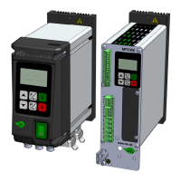
REOVIB MFS 368
Operating instructions
13
5.0 Ordering code (Standard units)
1 0 200 6368 2 1 2 1
Interfaces:
--- = without
EC = EtherCat
E I/P = EtherNet
PN = ProfiNet
DP = ProfiBus
CAN = CAN-Bus
DN = DeviceNet
EK = Input cable (open cable ends) V = Vertical design
AK = Output cable H = Horizontal design
AD = Output socket
PV = Plug & Vib
Control connections:
-Track control sensor
- Status relay
- Ready relay
- Enable input
- External setpoint 0...10 V, 0/4...20 mA
- Amplitude sensor
- Thermal switch (Series)
The following control connections are internally
included in all versions (IP54):
- Thermal switch (Series)
- External setpoint input: 0...10 V, 0/4...20 mA
0= ---
1= EC
2= E I/P
3= PN
4= DP
5= CAN
6= DN
1= 3 A
2= 6 A
3= 8 A
0= IP20 V
1= IP20 V UL
4= IP54 EK/AK
5= IP54 EK/AK UL
6= IP54 EK/AD
7= IP54 EK/AD UL
8= IP54 PV
9= IP54 PV UL
1= IP20 Basic
2= IP20 Series
4= IP54 Basic
5= IP54 Series

 Loading...