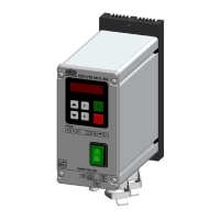
9.5 Diagnostic displays for non-optimized regulation settings
Controller has reached maximum output power.
The feedback signal from the sensor (accelerometer) is too weak relative to the
selected throughput setting.
Reduce Parameter “P“ in menu C 096 or C 008.
The feedback signal from the sensor (accelerometer) is too strong.
Alternating display:
The regulator oscillates rapidly.
Reduce Parameter “P.A“ in menu C 008.
10.0 Working frequency of the coil
With new applications the current should be monitored with a true RMS meter because it is possible to draw
a current that is too high for the coil, by changing the frequency, even by only a small amount.
The coil should be selected for the correct frequency, to prevent too high a current draw, resulting in over-
loading of the coil.
11.0 Measurement of output current and voltage
An effective measuring instrument that does not depend on a true sine wave for mains voltage or current,
should be used (a sine wave is only generated at full output with full wave control).
The output from frequency controllers is generated by an electronic inverter with pulse-width, modulated
switching. The voltage and current values cannot be measured with normal instruments. Preferably, a
moving-iron measuring instrument (analogue meter) should be used. An analogue meter is recommended
because electronic multi-meters, in this instance, will not measure reliably.
Recommended measuring equipment: REOVIB Measurement box 122
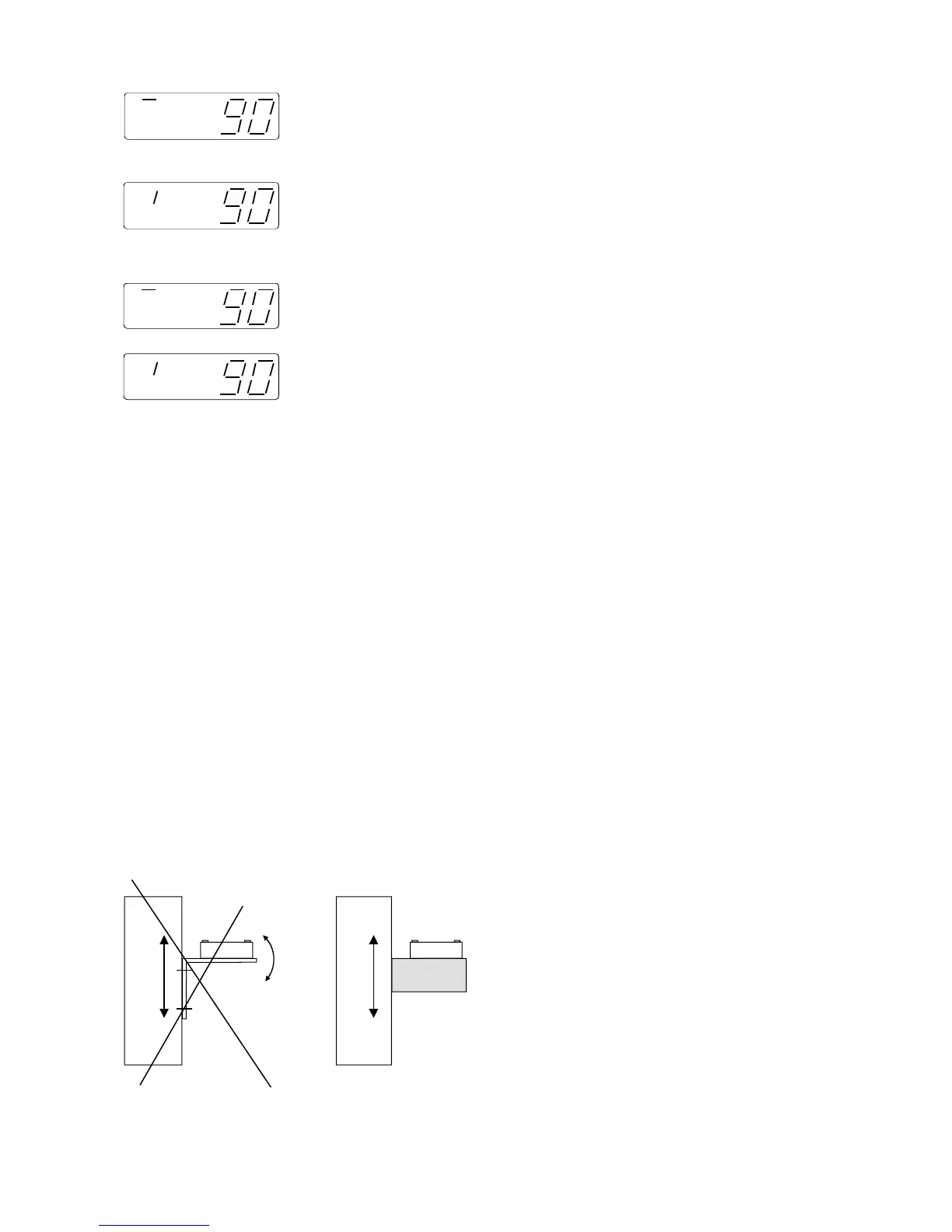
12.0 Accelerometer mounting
The accelerometer should generate signals for the movement and acceleration of the feeder, which are fed
back to the regulator circuit of the control unit. Therefore it is very important that the sensor picks up no other
extraneous vibration signals.
The sensor should be positioned so that it moves in
the same direction as the feeder, ideally in the same
plane as the springs, and it should be fitted on a solid
block that will not generate vibration signals.
18
 Loading...