3.2 Regulated drive control
It is possible to operate a vibratory feeder at resonance if a frequency inverter is used for holding the feeder
at resonant frequency and the amplitude at a level determined by a selected set-point. To achieve this, the
vibratory movement has to be measured and fed back to the frequency controller. Normally a sensor is fitted
to the vibrating part of the feeder to obtain this measurement. The signal generated is used not only to hold
the feeder at resonant frequency but also to maintain constant vibration amplitude by varying the output volt-
age. The feeder is always running with the greatest effectiveness when operating in this manner.
For more information refer to section 9.0 Guidance on using regulation control with frequency inverters.
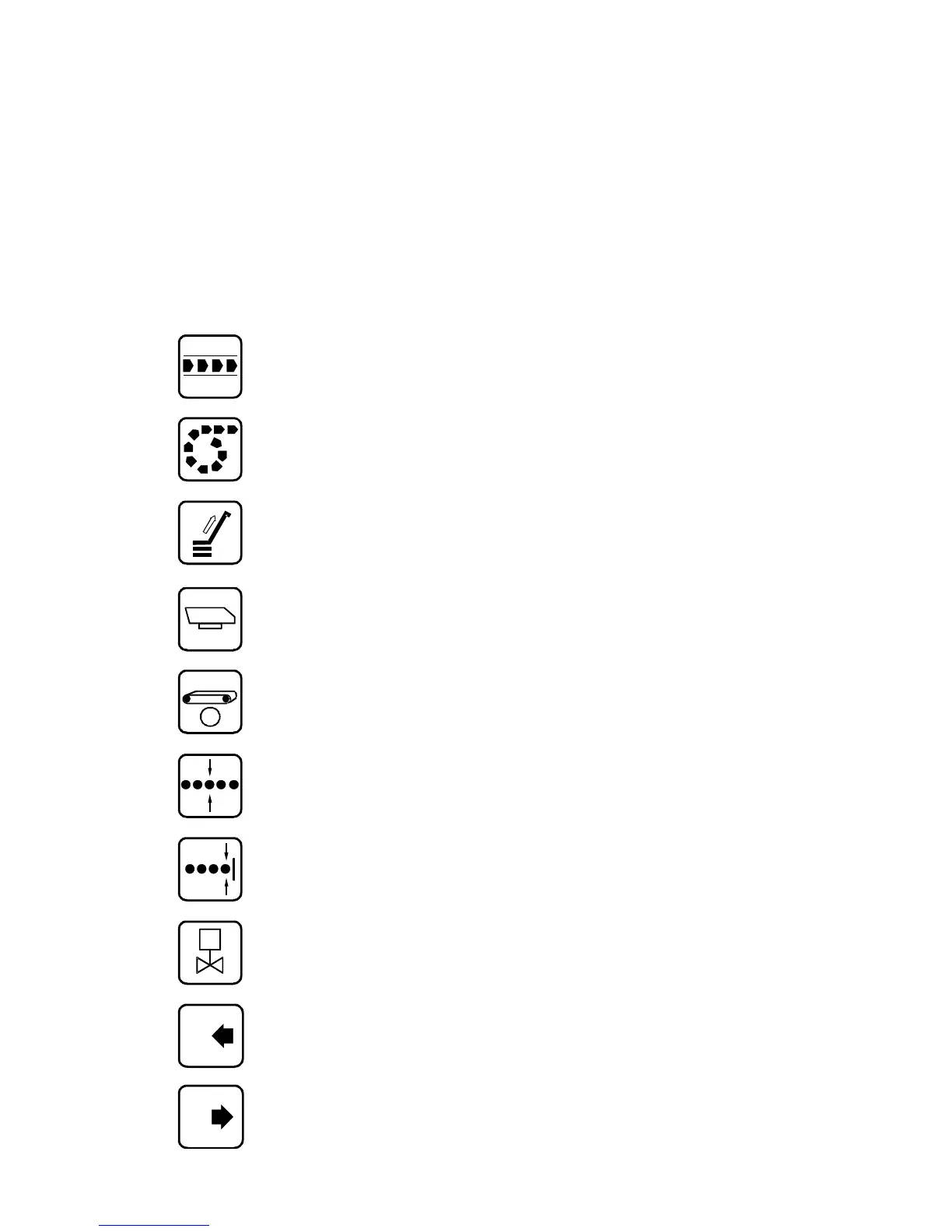
4.0 REOVIB – Symbols
The following icons are used to denote unit functions
Straight line vibratory feeder
Vibratory feeder with a spiral track
Motor driven pre-feeder
Vibratory pre-feeder
Belt pre-feeder
Track control (product line)
Sensor for level control
Solenoid valve, e.g. for air blast
Control input START / STOP
Control output ON / OFF
5
 Loading...