DeltaSol
®
B Pro
© RESOL 04026 deltasol_b_pro.mon.pmd
Page 5/24
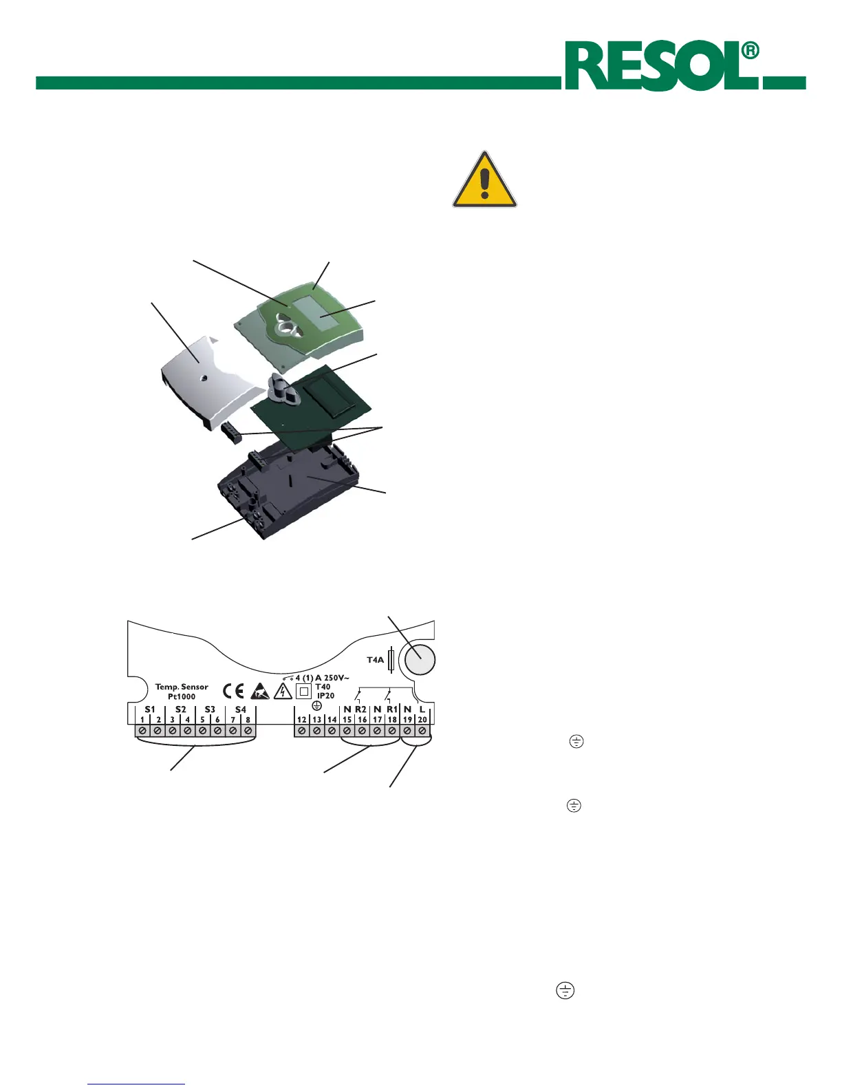
housing
key field
base
clamps
cover
cable conduits with strain relief
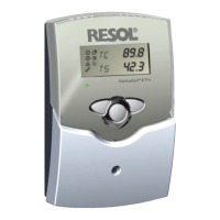
operation control lamp
combined LCD
1.1 Mounting
The unit must only be located internally. It is not suitable for
installation in hazardous locations and should not be sited
near to any electromagnetic field. The controller must
additionally be equipped with an all-polar gap of at least 3
mm or with a gap according to the valid installaton
regulations, e.g. LS-switches or fuses. Please pay attention
to a separate laying of the cable lines and installation of ac
power supply.
1. Unscrew the cross-recessed screw of the cover and
remove it from the housing.
2. Mark the upper fastening point on the underground and
premount the enclosed dowel and screw.
3. Hang up the housing at the upper fastening point and mark
the lower fastening point on the underground (hole pitch
130 mm), afterwards put the lower dowel.
4. Fasten the housing at the underground.
1. Installation
Warning!
Switch-off power supply before
opening the housing.
1.2 Electrical wiring
The power supply to the controller must only be made by
an external power supply switch (last step of installation!)
and the line voltage must be 210 ... 250 Volt (50...60 Hz). Fle-
xible lines are to be fixed at the housing by enclosed strain
relief supports and screws.
The controller is equipped with 2 standard relays, to which
the consumers e.g. pumps, valves etc. can be connected:
• Relay 1
18 = conductor R1
17 = neutral conductor N
13 = ground clamp
• Relay 2
16 = conductor R2
15 = neutral conductor N
14 = ground clamp
The temperature sensors (S1 up to S4) will be connected
to the following terminals independently of the polarity:
1 / 2 = Sensor 1 (e.g. Sensor collector 1)
3 / 4 = Sensor 2 (e.g. Sensor store 1)
5 / 6 = Sensor 3 (e.g. Sensor collector 2)
7 / 8 = Sensor 4 (e.g. Sensor store 2)
The power supply is effected to the clamps:
19 = neutral conductor N
20 = conductor L
12 = ground clamp
net clamps
protector
sensor clamps
consumer clamps
 Loading...


