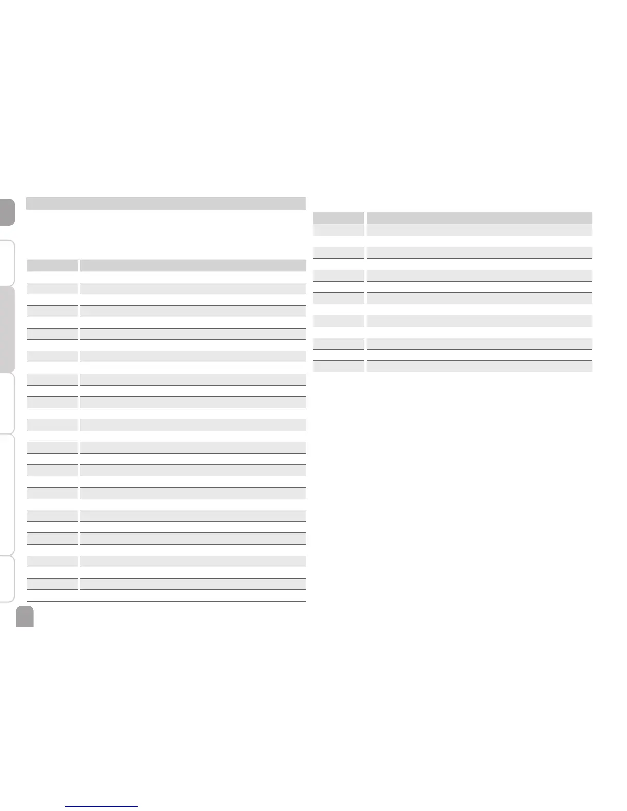
5 Status level / Measurement values
During normal operation of the controller, the display is in the status level. This one
indicates the measurement values shown in the table.
In addition to the display values, possible error messages are indicated in the status
level (see page 69).
Display Description
BLPR1 Blocking protection R1
BLPR2 Blocking protection R2
BLPR3 Blocking protection R3
INIT Initialisation
FLLT Filling time
STAB Stabilisation
TCOL Temperature collector
TCOL1 Temperature collector 1
TCOL2 Temperature collector 2
TSTB Temperature store base
TST1B Temperature store 1 base
TSTT Temperature store top
TST2B Temperature store 2 base
TSFL Temperature solar ow
TSRE Temperature solar return
TSFB Temperature solid fuel boiler
TSTR Temperature store return preheating
TRET Temperature return
S3 Temperature sensor 3
S4 Temperature sensor 4
S5 Temperature sensor 5
n1 Speed relay 1
n2 Speed relay 2
n3 Speed relay 3
n4 Status relay 4
h R1 Operating hours relay 1
h R2 Operating hours relay 2
h R3 Operating hours relay 3
h R4 Operating hours relay 4
Display Description
L/h Flow rate Grundfos Direct Sensor
TM
BAR System pressure
TSFL Temperature solar ow VFS
TSRE Temperature solar return RPS
TFHQM Temperature ow heat quantity measurement
TRHQM Temperature return heat quantity measurement
L/h Flow rate V40 or ow gauge
kWh Heat quantity in kWh
TDIS Disinfection temperature
CDIS Countdown thermal disinfection
DDIS Heating period thermal disinfection
TIME Time
DATE Date
* R4 is an electromechanical relay not suitable for speed control. Therefore, its status is
indicated with 0 % or 100 % respectively.

 Loading...