Depending on the product version, mains cables and sensor cables are already
connected to the device. If that is not the case, please proceed as follows:
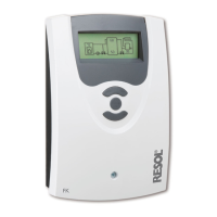
Connect the temperature sensors (S1 to S5) to the corresponding terminals
with either polarity:
S1 = Sensor 1 (collector sensor )
S2 = Sensor 2 (store sensor base)
S3 = Sensor 3 (e. g. store sensor top)
S4 = Sensor 4 (e. g. store sensor store 2)
S5 = Sensor 5 (e. g. sensor collector 2)
Connect the Grundfos Direct Sensors™ to the inputs marked VFS and RPS.
A V40 owmeter can be connected to the terminals V40 and GND (either po-
larity).
The terminals marked PWM are control outputs for high-efciency pumps (PWM1
is allocated to R1, PWM2 is allocated to R2).
R1-R3
R4
R4
VBus
VBus
GND
V40
PWM 2
PWM 1
S5
S4
S3
GND
N
VFS
DeltaSol
®
BX
Made in Germany
RPS
Temp. Sensor
Pt1000
S2
S1
R3
R2
R1
L'
L
IP 20
1 (1) A (100 ... 240) V~
2 (1) A (100 ... 240) V~
100 ... 240 V~
T4A
50-60 Hz
The mains connection is at the terminals:
Neutral conductor N
Conductor L
Conductor L' (L' is not connected with the mains cable. L' is a fused contact
permanently carrying voltage.)
Protective conductor ⏚
Note:
For further information about heat quantity measurement with Grund-
fos Direct Sensors™ see page 64.
Note:
The connection depends on the system layout selected (see page 7).
Note:
For more details about the commissioning procedure see page 39.
2.3 Data communication / Bus
The controller is equipped with a RESOL VBus
®
for data transfer and energy
supply to external modules. The connection is to be carried out at the terminals
marked VBus (either polarity).
One or more RESOL VBus
®
modules can be connected via this data bus, such as:
• RESOL GA3 Large Display module / SD3 Smart Display
• RESOL AM1 Alarm Module
• RESOL DL2 Datalogger
• RESOL DL3 Datalogger
Furthermore, the controller can be connected to a PC or integrated into a net-
work via the RESOL VBus
®
/USB or VBus
®
/LAN interface adapter (not includ-
ed). Different solutions for visualisation and remote parameterisation are available
on the RESOL website www.resol.com.
Note:
More accessories on page 72.
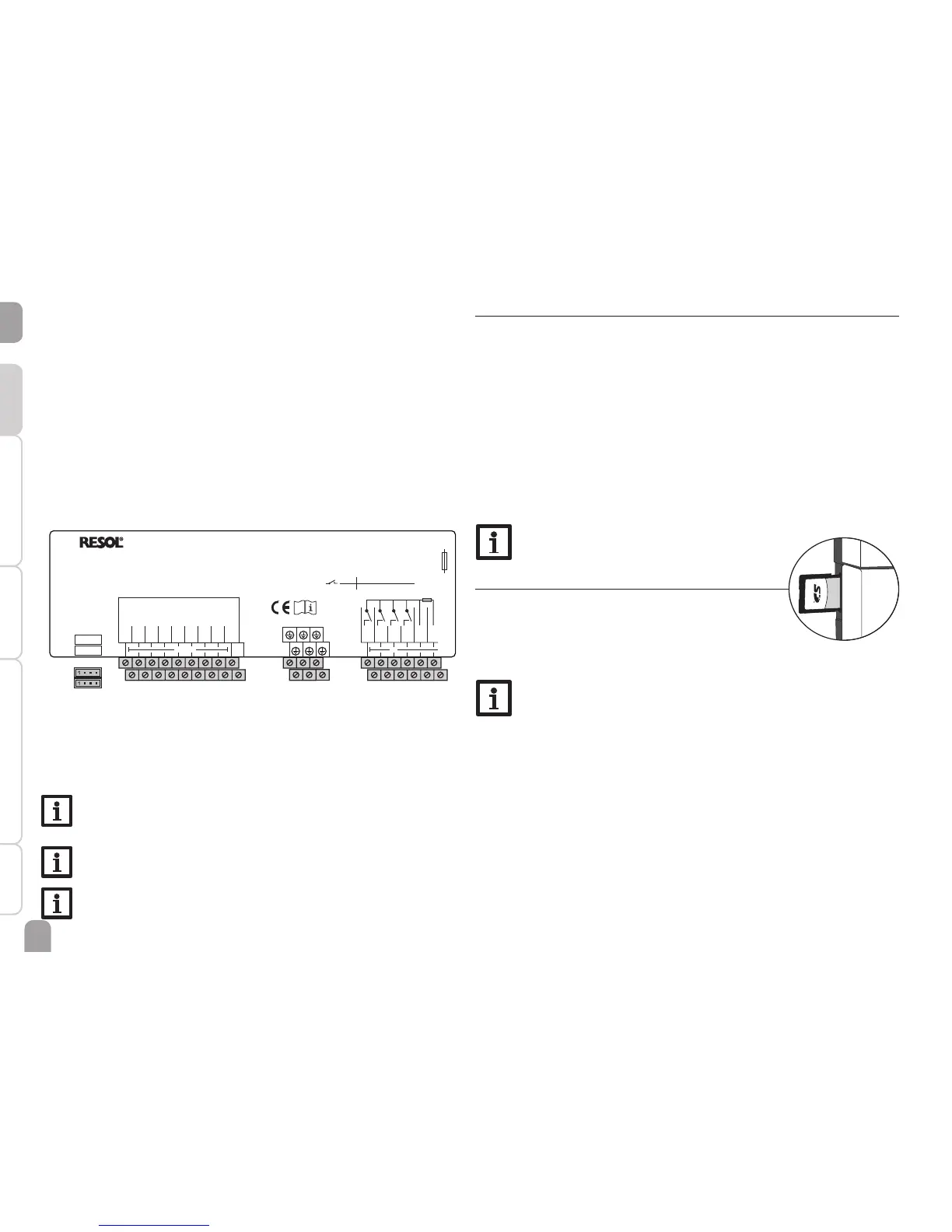
2.4 SD memory card slot
The controller is equipped with an SD card slot.
With an SD card, the following functions can be carried out:
• Store measurement and balance values onto the SD
card. After the transfer to a computer, the values can be
opened and visualised, e. g. in a spreadsheet.
Note:
For more information about using an SD card, see page 66.
 Loading...