REV-11-1200-UM-00 Copyright © 2016 REV Robotics, LLC 11
2.4 LIMIT SWITCH INPUTS
The SPARK has two limit switch inputs that, when triggered, can independently prevent motion in both the forward and
reverse directions.
2.4.1 LIMIT SWITCH O PERATIO N
When the signal (s) pin is shorted to the ground (-) pin, the SPARK will override an input command for the corresponding
direction and force the SPARK to its neutral state. The STATUS LED will turn white and pulse the corresponding
direction color when either of the two limits are triggered and overriding the input command. See section 2.6 STATUS
LED for more information.
For example, if the Forward Limit Switch is triggered, a forward command from the PWM input is overridden and the
output is forced into its neutral state. However, reverse commands are still accepted and sent to the output.
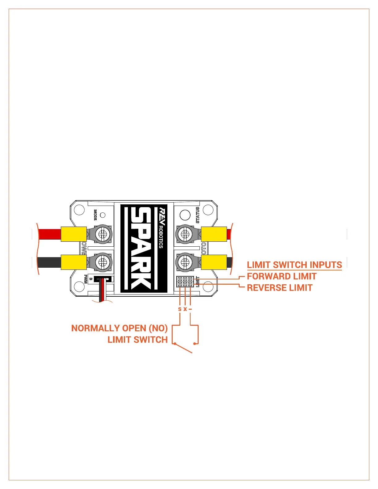
2.4.2 LIMIT SWITCH WIRI NG
The SPARK has two 3-pin connectors that can accept standard 3-wire sensor cables. The center pin is not used for the
limit switch inputs. Figure 2-4 shows the locations of the Forward and Reverse ports and an example connection
diagram. It is recommended to use a limit switch that is Normally Open (NO). When it is pressed, the switch closes and
shorts the signal (s) and ground (-) pins.
Figure 2-4 Limit Switch Inputs