REV-11-1200-UM-00 Copyright © 2016 REV Robotics, LLC 6
1.3 SPECIFICATIONS
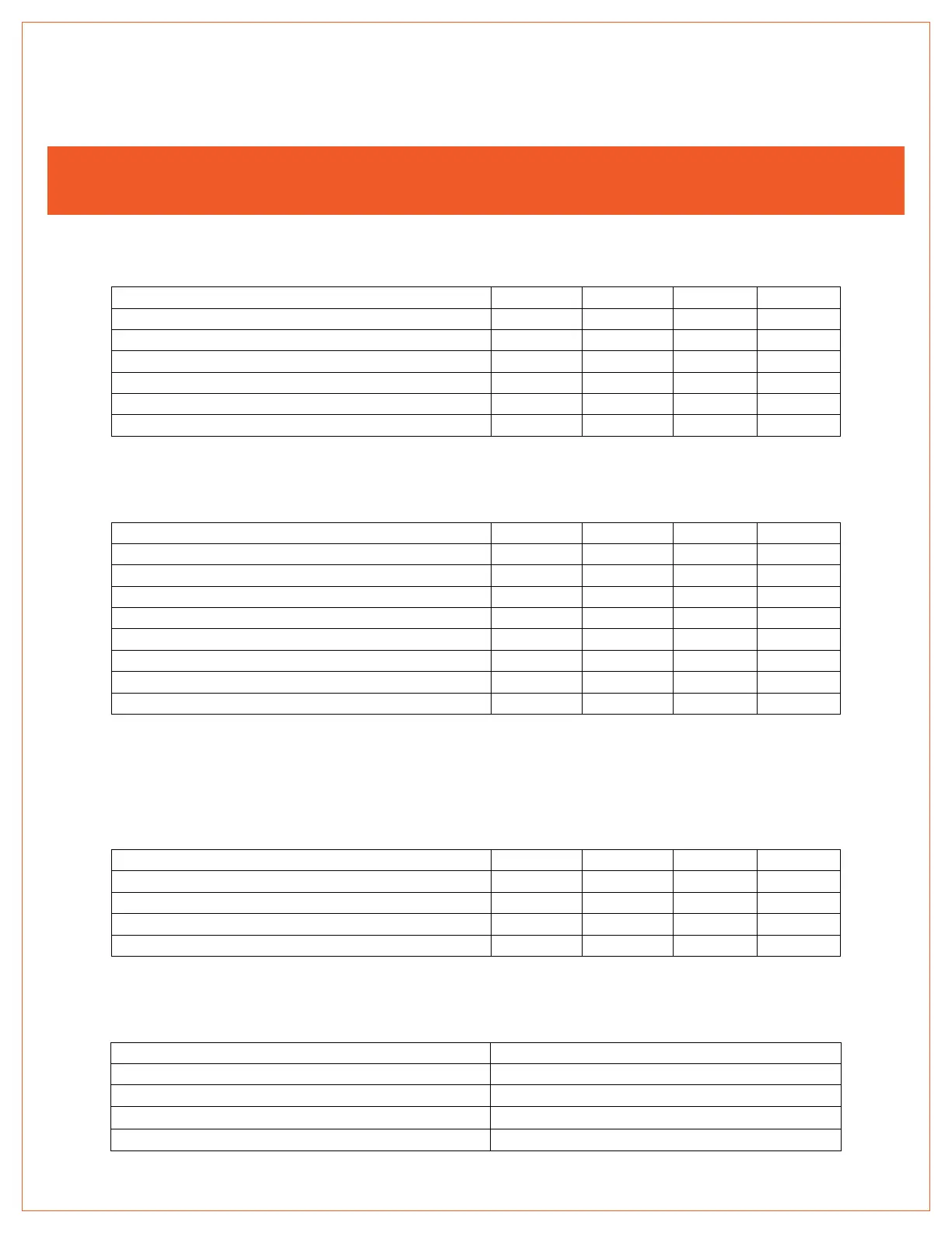
The following tables provide the operating and mechanical specifications for the SPARK motor controller.
CAUTION
DO NOT exceed the maximum supply voltage or maximum current rating. Doing so will cause permanent damage to the
SPARK and will void the warranty.
Table 1-1 Electrical Specifications
Supply voltage range (V
IN
)
Supply voltage absolute maximum
Continuous output current
Maximum output current - for 2 seconds
a. Continuous operation at 60A may produce high temperatures on the heat sink. Caution should be taken when handling a
SPARK if it has been running at higher current levels for an extended period of time.
Table 1-2 Servo-PWM Input Specifications
Default full-reverse input pulse
a
Default neutral input pulse
b
Default full-forward input pulse
c
Digital high-level input current
a. Full-reverse corresponds to negative output voltage (-V
IN
).
b. Neutral corresponds to zero output voltage (0V) and is either braking or coasting depending on the current mode.
c. Full-forward corresponds to positive output voltage (+V
IN
).
d. If a valid pulse isn't received within the timeout period, the SPARK will disable its output.
e. Input deadband is added to each side of the neutral pulse width. Within the deadband, output state is neutral.
Table 1-3 Limit Switch Input Specifications
Digital low-level input voltage
a
Digital high-level input voltage
b
a. Disables motion in corresponding direction.
b. Enables motion in corresponding direction.
Table 1-4 Mechanical Specifications