REV-11-1200-UM-00 Copyright © 2016 REV Robotics, LLC 7
2 FEATURE DESCRIPTION
The REV Robotics SPARK Motor Controller includes a range of features designed specifically for use on FIRST®
Robotics Competition robots. Each feature is described in detail throughout the following sections.
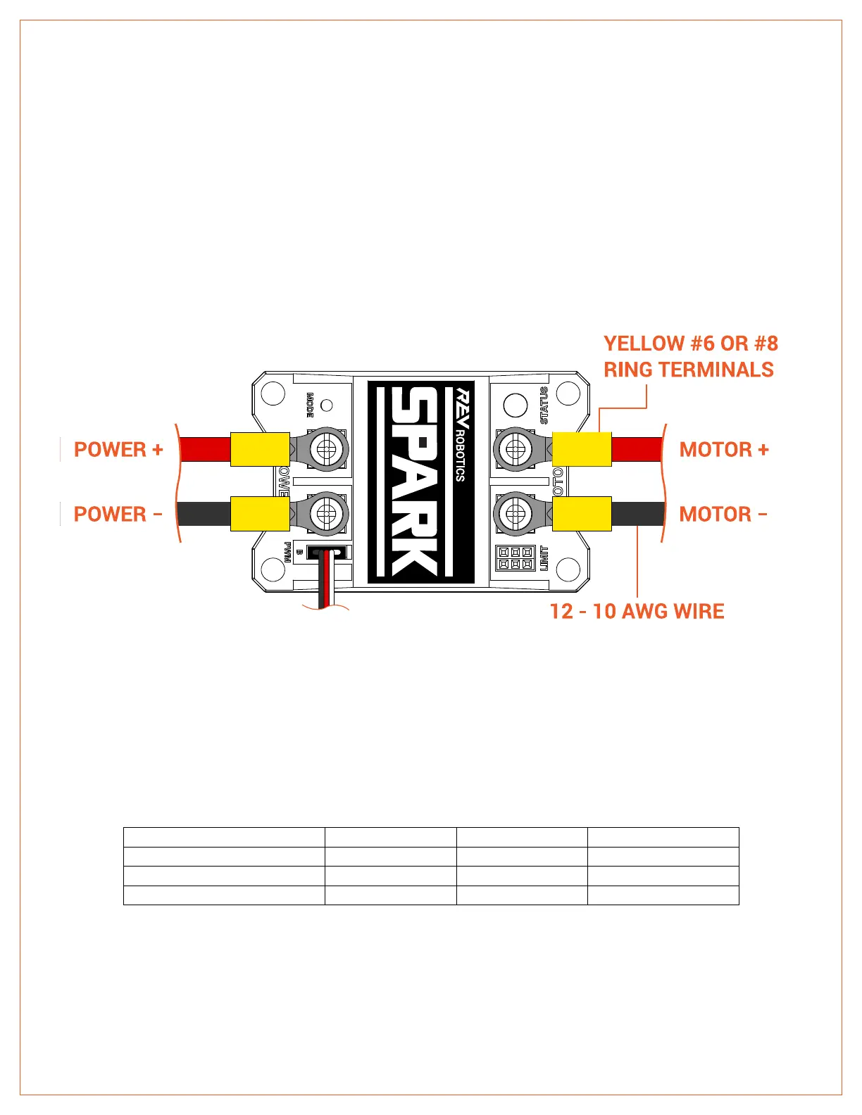
2.1 POWER AND MOTOR CONNECTIONS
The SPARK is designed to drive 12V brushed DC motors at currents up to 60A continuously. Power and motor
connections are made through the two sets of screw terminals built into the SPARK. Figure 2-1 shows these
connections in detail.
Figure 2-1 Power and Motor Connections
2.1.1 SCREW T ERMINAL S
The SPARK has four M3 sized screw terminals; two each for power and motor connections. Each screw has a clamping
washer that improves the contact area and clamping force compared to plain screw heads. Table 2-1 lists the
recommended crimp-terminal sizes and styles.
Table 2-1 Compatible Crimp-terminal Sizes