ILLUSTRATED PARTS MANUAL
LM35, LM45 LAMINATORS
Rexel Business Machines, Westbank, Droitwich Spa, Worcestershire. WR9 9AP England
Tel: +44 (0) 1905 771555 Fax: +44 (0) 1905 823374
13
5 To reassemble, fit frame back on to rollers/bearings, paying
particular attention to locating the heater assemblies properly
(refer section 7).
6 Fit and connect up lever arms and springs, replace idler gear and
thermal fuse.
7 Fit head and top cover (sections 3, 2 and 1).
RIGHT HAND SIDEFRAME
1 Remove the motor as described in section 4 (no need to extract
motor wires from PCB connector).
2 Remove ‘motor end’ springs and lever arms (Section 6).
3 Remove top heater earth connection from its stud.
4 Remove the wire to the lower heater from the PCB connector.
5 Cut link wire between the heaters.
6 Slide sideframe off roller spindles/bearings and extract wires
through hole in lower part of the frame.
7 Replace side frame and re-assemble the head, generally as
described in section 7, RE-ASSEMBLY, 1 to 5.
8 Route wires through hole in side frame, or over the top as
described in section 9, and re-join the heater link wires using a
suitable butt connector.
9 Refit motor (Section 4).
10 Replace head and top cover (Sections 3, 2 & 1).
SECTION 10
Removal and Replacement of Front Shelf Moulding
1 Remove top cover/PCB, and head (Sections 1, 2 & 3).
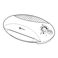
2 Remove keypad membrane and plastic LCD cover.
3 Remove the two top to bottom ‘ellipse’ fixing screws.
4 Unclip top cover (ellipse) from base by sliding it forward and out.
Reassemble in reverse sequence.
5 Re-assemble in reverse sequence.