2.2 Power Terminals
The table below describes the symbols on the frequency converter's power con-
nection terminals and their function.
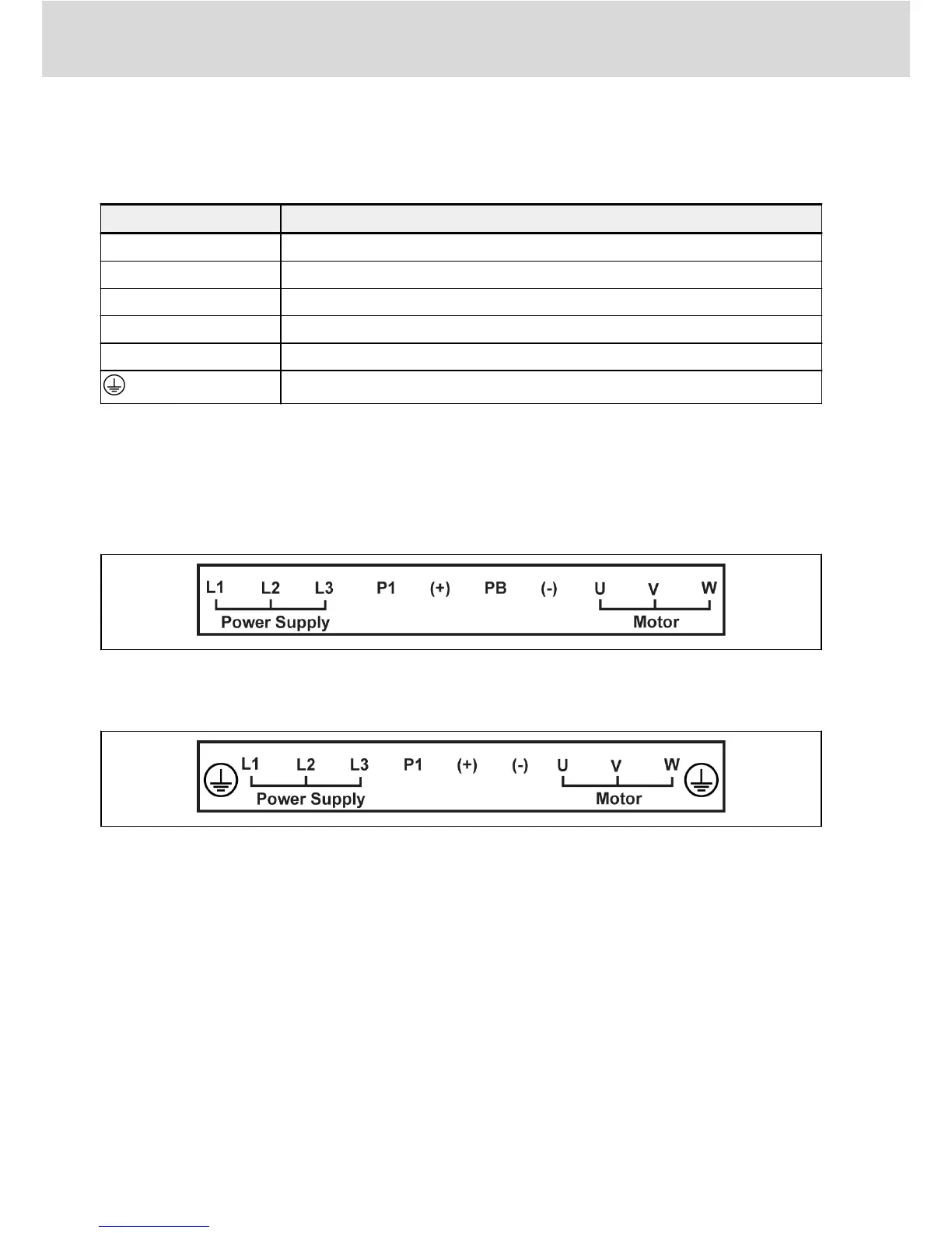
Terminal Description
L1, L2, L3 Mains supply input terminals
U, V, W Frequency converter output terminals
PB External brake resistor terminal (Only applicable to 0K40...15K0 models)
P1, (+) DC choke input or DC positive bus output terminal
(-) DC negative bus output terminal
Grounding terminal
Tab. 2-3: Power terminals description
Depending on size, the position and order of the power terminals on the individ-
ual frequency converter may differ. Refer to the graphics below for the exact
connection terminal position and sequence:
0K40...15K0
Fig. 2-2: Frame 1, 2, 3
18K5...90K0
Fig. 2-3: Frame 4, 5, 6, 7
Bosch Rexroth AG
Electric Installation
12/39
DOK-RCON02-FV*********-IN05-EN-P

 Loading...


