2.3 Interface Connection for Signals
2.3.1 Jumper Wiring
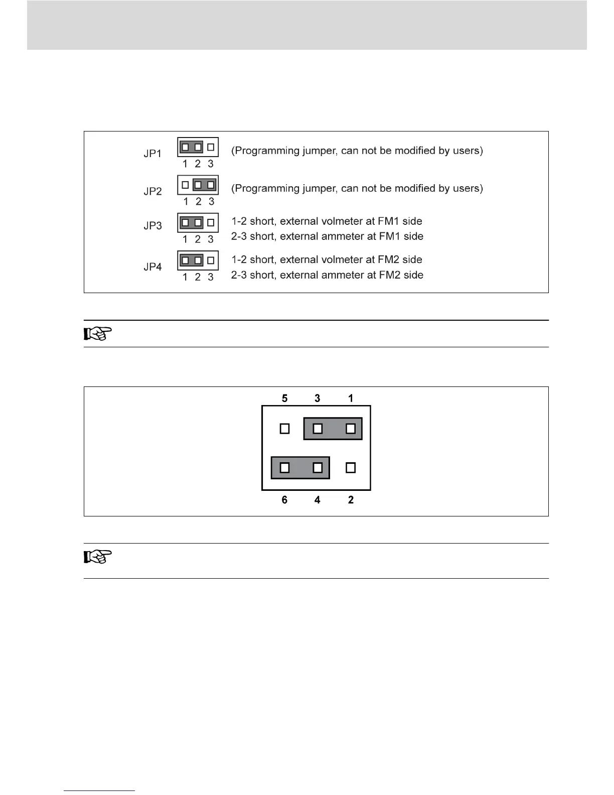
Fig. 2-4: Jumper description
Shown above are factory defaults.
2.3.2 NPN / PNP Jumper SW1
Fig. 2-5: NPN/PNP jumper SW1
The factory default for the jumper is NPN (Jumper contact at 1-3,
4-6).
The jumper SW1 determines:
1. The internal 24 V power supply or an external 24 V power supply is used
for the inputs.
2. The inputs are activated by connection of 24 V to an input (PNP / active in-
put) or connection of 0 V to an input (NPN / passive input).
Modes and signal inputs:
The jumper SW1 can switch between 0 V (NPN / passive input) and +24 V (PNP /
active input) inputs, respective external +24 V power supply is also available,
which improves the flexibility of signal input mode.
Bosch Rexroth AG
Electric Installation
DOK-RCON02-FV*********-IN05-EN-P
13/39

 Loading...


