13
I-UEZ (04-21) 1034347-0
Technical Data
⚠ CAUTION ⚠
DO NOT use copper or copper-based alloys for condensate drains.
• The combustion process forms condensation, which is collected and directed to a drainage point inside the unit.
The heater is equipped with a 1/2-inch (12.7-mm) PVC pipe for connecting to a condensate drain. The water
condensed from the products of combustion will be acidic. The level of concentration is dependent upon the
environment where the appliance is installed and may be as high as 6 pH.
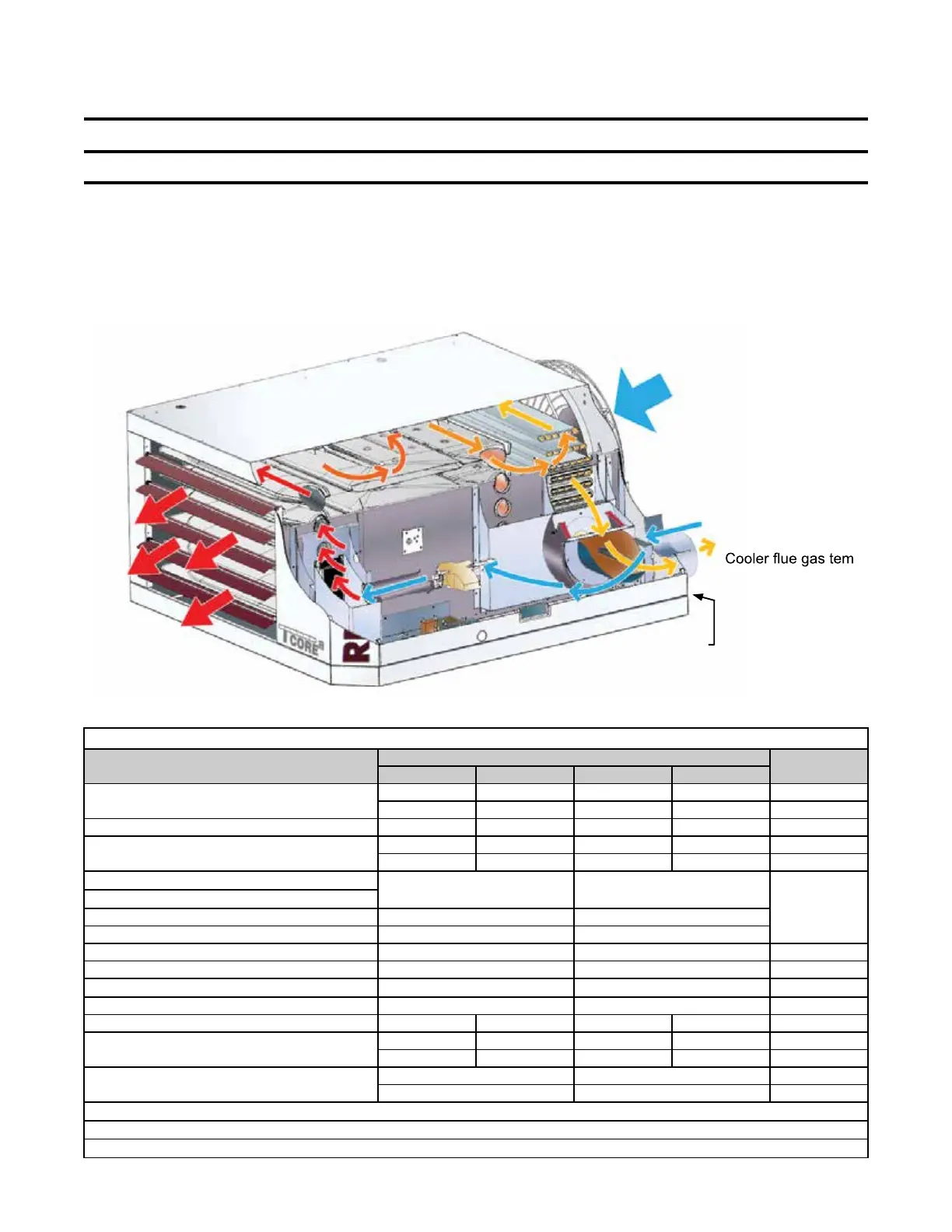
• The unit’s operating principle showing combustion airflow and supply airflow is shown in Figure 5. Related technical
data is listed in Table 10.
Figure 5. Combustion Airflow and Supply Airflow
Room Supply Air
Intake
Warm
Air
Discharge
Flue Gas Outlet
perature requires a
the vent.
Condensate
drain connection from
the secondary heat exchanger
Outside
Combustion Air to
the Burner
Table 10. Technical Data
Parameter
Unit Size
Unit of
Measurement
130 180 260 310
Input heating capacity
131,000 175,000 260,000 305,000
BTUh
38.4 51.2 76.1
89.3 kWh
Thermal efficiency 93 91 92 91 %
Output heating capacity*
121,830 159,250 239,200 277,550 BTUh
35.7 46.6 70.0 81.3 kWh
Gas connection, natural**
1/2 3/4
Inches
Gas connection, propane**
Vent connection diameter 4 4
Combustion air inlet diameter 6 6
Control, 24V 1.0 1.0 Amps
Full load amps, 115V 6.3 10.0
Maximum overcurrent protection, 115V***
15.0 20.0 Amps
Normal power consumption 657 1020 Watts
Discharge air temperature rise 50 60 50 60 °F
Air volume
2256 2458 4430 4283 cfm
63.9 69.6 125.4 121.3 Meter
3
/minute
Discharge air opening area
2.56 4.79 Foot
2
0.2 0.5 Meter
2
*CSA ratings for elevations up to 2,000 feet.
**Size shown is for gas connection to a single-stage gas valve—not supply line size.
***MOCP = 2.25 × (largest motor FLA) + smallest motor FLA. Answer is rounded to the next lower standard circuit breaker size.

 Loading...


