INSTALLATION—CONTINUED
Heat Exchanger Condensate Drain Installation
Install the heat exchanger condensate drain in accordance with all piping requirements listed in this manual and
with Figure 18.
Electrical Connections
⚠ CAUTION ⚠
• Route wires so that they do not contact the flue wrapper or venter housing.
• If any of the original wire supplied with the appliance must be replaced, it must be replaced with
wiring material having a temperature rating of at least 105°C, except for limit control, flame rollout,
and sensor lead wires which must be rated at 150°C.
NOTES:
• Specific wiring diagrams that include standard and factory-installed options are provided with
the unit. Ensure that all wiring is in accordance with these wiring diagrams.
• A two-stage valve circuit is NOT available on all models.
• All electrical wiring and connections, including electrical grounding MUST be made in accordance with the National
Electric Code ANSI/NFPA No. 70 (latest edition) or, in Canada, with CSA Standard C22.1. In addition, the installer
should be aware of any local ordinances or gas company requirements that might apply.
• Check the rating plate on the heater for the supply voltage and current requirements. A dedicated line voltage
supply with a disconnect switch should be run directly from the main electrical panel to the heater.
• All external wiring must be within approved conduit and have a minimum temperature rise rating of 60°C. Conduit
must be run so as not to interfere with the heater access panel.
• If the installation requires a stepdown transformer (option CG), follow the instructions shipped with the option
package for installing the transformer.
• The unit includes a built-in disconnect switch (20A@115V or 10A@230V rating).
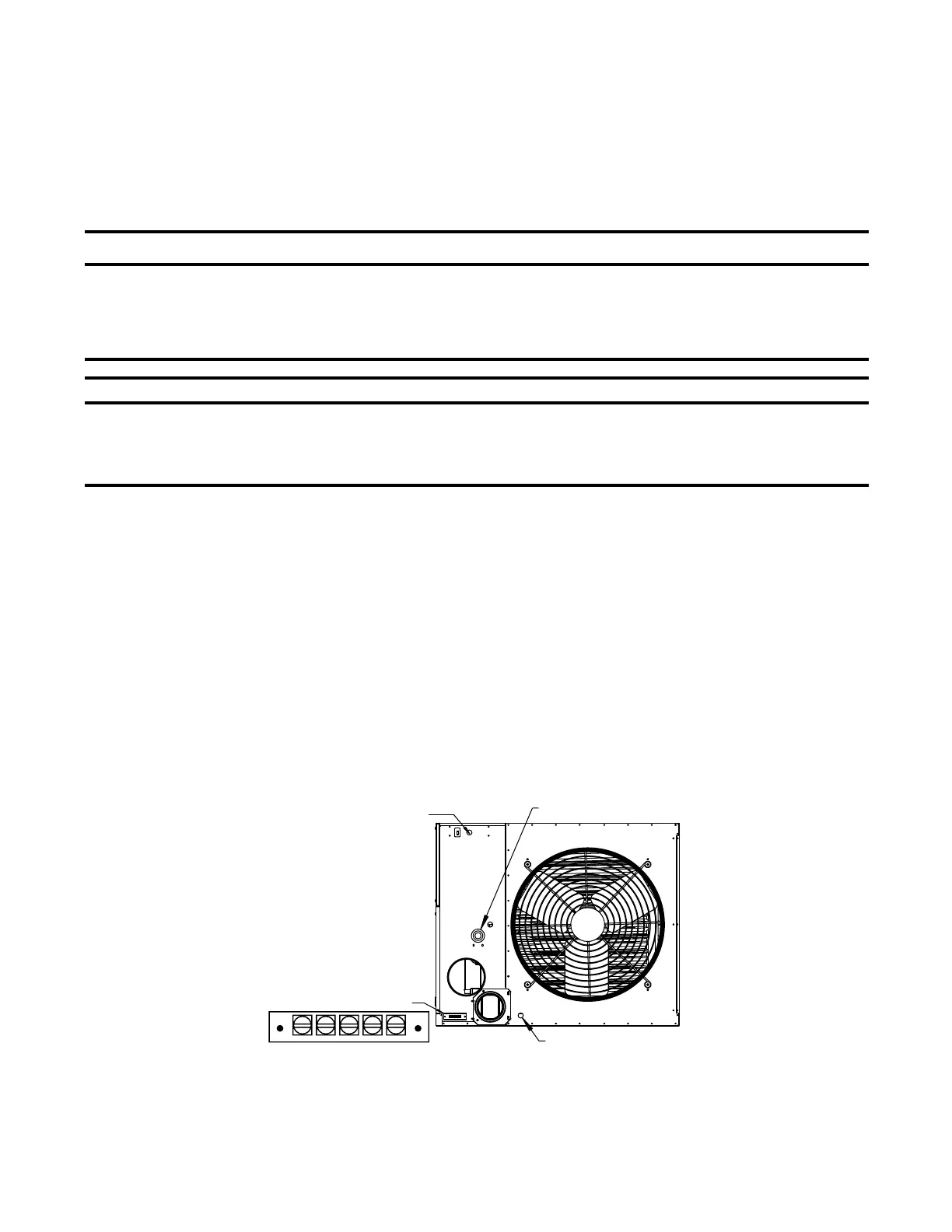
• The supply wiring enters at the rear of the heater, as shown in Figure 23. Supply wiring connects to leads located
inside a sealed electrical box. To maintain the sealing feature of the electrical box, always replace the cover plate.
• The terminal strip for the 24V thermostat connections is located on the outside of the cabinet at the back of the
heater, as shown in Figure 23. Wires from the terminal strip are factory-wired to the circuit board.
Figure 23. Supply Wiring Entrance and Control Connection Terminal Strip
• The circuit board (see Figure 24) is located inside on the bottom of the control compartment. The circuit board is
polarity sensitive. It is advisable to check the electrical supply ensure that the black wire is the hot wire and that
the white wire is the neutral wire. The hot wire must be connected to terminal L1 on the circuit board.
Condensate Drain
Line Voltage
Entrance
Terminal Strip for
Thermostat
Connection
R GW1
C
32
I-UEZ (04-21) 1034347-0

 Loading...


