8
I-UEZ (04-21) 1034347-0
GENERAL INFORMATION—CONTINUED
Dimensions—Continued
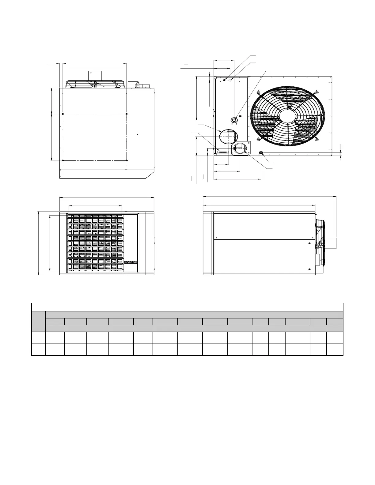
Figure 2. Dimensions (Refer to Table 4)
Table 4. Dimensions
Unit
Size
Dimension (See Figure 2)
A B C E F G H J K M N P R S
Inches (±1/8) (mm (±3))
130,
180
20-1/8
(511)
39-3/16
(
995)
16-1/16
(
408)
11-31/32
(
304
)
2-3/8
(
60
)
25-11/16
(
652
)
55-13/32
(1407)
46-1/32
(1169)
15-19/32
(396)
8-5/16
(
211
)
4-5/16
(
110
)
5-1/16
(
129
)
6-9/32
(160)
1-3/4
(
45
)
260,
310
34-1/8
(867)
41
(1041)
30
(762)
13-31/32
(355)
1-13/32
(36)
27-11/16
(703)
58
(1473)
48-21/32
(1236)
16-15/32
(418)
9-3/32
(
231
)
5-3/32
(
129
)
18-13/16
(
478
)
7 1/32
(179)
1-3/8
(
35
)
A
C
23" (584 mm)
B
FRONT VIEW
25" (635 mm)
E
F
G
TOP VIEW
FOUR SUSPENSION POINTS
(3/8 - 16 FEMALE THREAD)
J
H
RIGHT SIDE VIEW
1
9
16
" (40 mm)
5
5
8
" (143 mm)
R
P
N
M
K
S
3
3
16
" (81 mm)
8
3
16
" (208 mm)
REAR VIEW
DISCONNECT SWITCH
LINE VOLTAGE ENTRANCE
(CONNECTS IN SEALED ELECTRICAL BOX)
EXTERNAL GAS CONNECTION
6" COMBUSTION
AIR CONNECTION
CONDENSATE DRAIN
4" VENT CONNECTION
THERMOSTAT
CONNECTION
Clearances
Units must be installed so that the clearances listed in Table 5 are provided for with regards to combustion air space,
inspection, and service and for proper spacing from combustible construction. Clearance to combustibles is defined
as the minimum distance from the heater to a surface or object for which it is necessary to ensure that a surface
temperature of 90°F (50°C) above the surrounding ambient temperature is not exceeded. Refer to the dimensions
listed in Table 4 and shown in Figure 2 when determining clearances to combustibles.

 Loading...


