6
I-UEZ (04-21) 1034347-0
GENERAL INFORMATION—CONTINUED
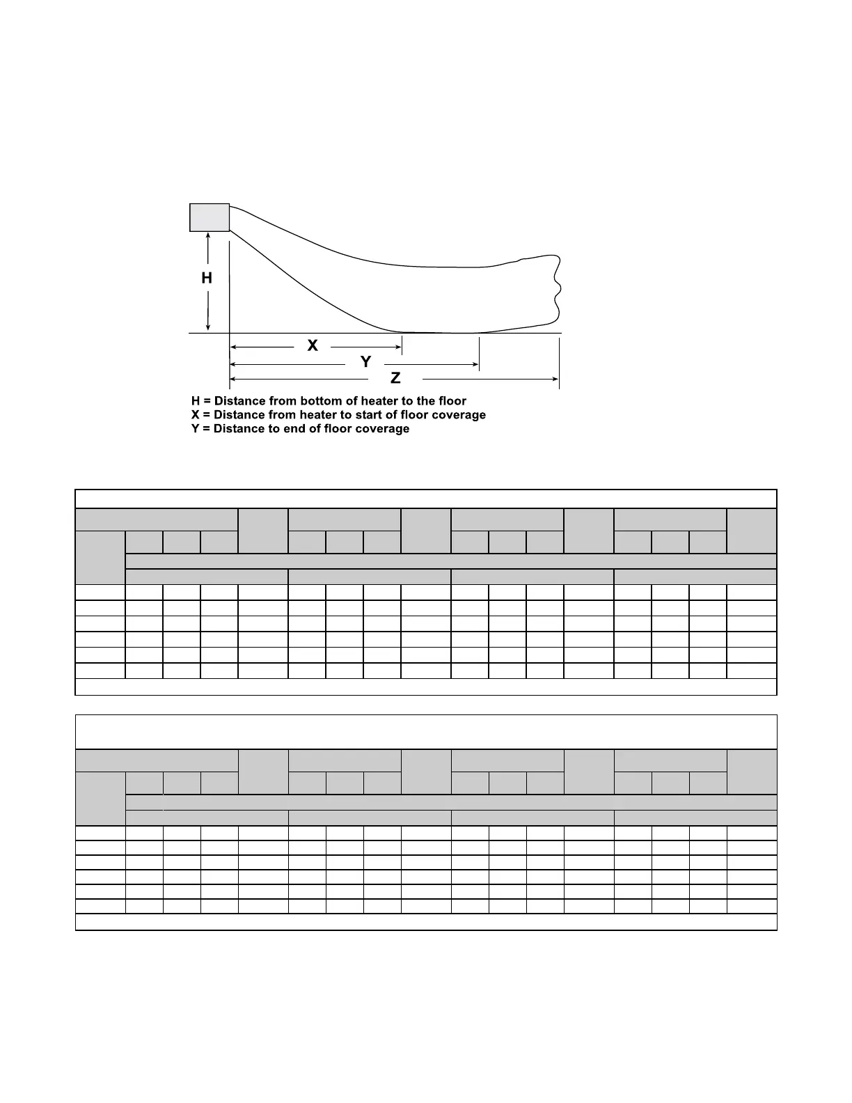
Heater Throw
Figure 1 shows throw patterns for fan model units. Table 2 and Table 3 list throw distances for standard, adjustable
horizontal louvers at the angles listed. The louver angles listed are relative to the top of the heater. The throw pattern
changes with the addition of optional vertical louvers and/or downturn nozzles.
Z = Distance at which air velocity drops below 50 feet (15.2 meters) per minute
Figure 1. Heater Throw Patterns (Refer to Table 2 and Table 3)
Table 2. Heater Throw Distances with Standard Horizontal Louvers at Mounting Heights of 8 to 18 Feet
Distance*
Louver
Angle
Distance*
Louver
Angle
Distance*
Louver
Angle
Distance*
Louver
Angle
H
X Y Z X Y Z X Y Z X Y Z
Unit Size
130 180 260 310
8 13 24 73 −26° 16 30 93 −20° 15 28 94 −24° 17 31 105 −20°
10 14 24 69 −32° 17 31 91 −25° 16 28 89 −29° 18 32 103 −25°
12
14 24 64 −39° 18 31 88 −30° 17 28 85 −34° 19 32 98 −30°
14 14 22 59 −45° 19 30 84 −34° 17 27 80 −40° 20 32 95 −34°
16
13 20 53 −51° 19 29 79 −39° 17 25 74 −45° 21 31 90 −38°
18 11 17 44 −58° 19 28 74 −44° 16 24 66 −51° 20 30 85 −43°
*Distance in feet (see Figure 1).
Table 3. Heater Throw Distances with Standard Horizontal Louvers at Mounting Heights of
2.4 to 5.5 Meters
Distance*
Louver
Angle
Distance*
Louver
Angle
Distance*
Louver
Angle
Distance*
Louver
Angle
H
X Y Z X Y Z X Y Z X Y Z
Unit Size
130 180 260 310
2.4 4 7 22 −26° 5 9 28 −20° 5 9 29 −24° 5 9 32 −20°
3.0 4 7 21 −32° 5 9 28 −25° 5 9 27 −29° 6 10 31 −25°
3.7 4 7 20 −39° 6 9 27 −30° 5 9 26 −34° 6 10 30 −30°
4.3 4 7 18 −45° 6 9 26 −34° 5 8 24 −40° 6 10 29 −34°
4.9 4 6 16 −51° 6 9 24 −39° 5 8 23 −45° 6 9 27 −38°
5.5 3 5 13 −58° 6 9 23 −44° 5 7 20 −51° 6 9 26 −43°
*Distance in meters (see Figure 1).

 Loading...


