Measure and Adjust Manifold Gas Pressure—Elevation >2,000 Feet (>610 Meters)
For installations at high elevations, measure and adjust the manifold (outlet) gas pressure as follows:
1. If installation is at elevation >6,000 feet (1,830 meters), replace pressure switch in accordance with Pressure
Switch Replacement section.
2. Determine correct outlet pressure (refer to Table 23) for elevation of installation. If unsure of elevation, contact
local gas supplier.
3. Turn knob or switch on top of valve to OFF to prevent flow to gas valve.
NOTE: A manometer (fluid-filled gauge) is recommended rather than a spring-type gauge due to
the difficulty of maintaining the calibration of a spring-type gauge. Use a water column manometer
that is readable to the nearest tenth of an inch.
4. Connect manometer to 1/8-inch output pressure tap on valve (see Figure 28).
5. Turn knob or switch on top of valve to ON.
6. Remove cap from regulator screw (see Figure 28) and adjust pressure in accordance with Table 23 by turning
regulator screw IN (clockwise) to increase pressure or OUT (counterclockwise) to decrease pressure.
7. Turn up thermostat. Depress and hold door safety switch.
8. Cycle burner once or twice to properly seat adjustment spring in valve and recheck outlet pressure. When pressure
corresponds to Table 23, disconnect manometer and install cap on regulator screw.
9. Check for leakage at 1/8-inch outlet pressure tap fitting. Correct as necessary.
10. Connect manometer to inlet pressure tap (see Figure 28). While heater is operating, measure inlet pressure,
which should be between 5 and 13.5 IN WC for natural gas or between 10 and 13.5 IN WC for propane.
11. If inlet pressure is not between 5 and 13.5 IN WC for natural gas or between 10 and 13.5 IN WC for propane,
inlet pressure must be corrected by adjusting manifold (outlet) pressure in accordance with steps 3 through 6.
NOTE: The inputs and capacity of the heater varies depending on elevation.
12. Refer to Table 24 or Table 25 for input and capacity values for elevation of installation.
a. Use permanent marker to fill in appropriate input and capacity values on high-elevation adjustment label from
literature bag provided with unit.
b. Select location for label on outside of heater access panel that will be conspicuous to anyone operating or
servicing unit.
c. Ensure that surface is clean and dry and affix label.
45
I-UEZ (04-21) 1034347-0
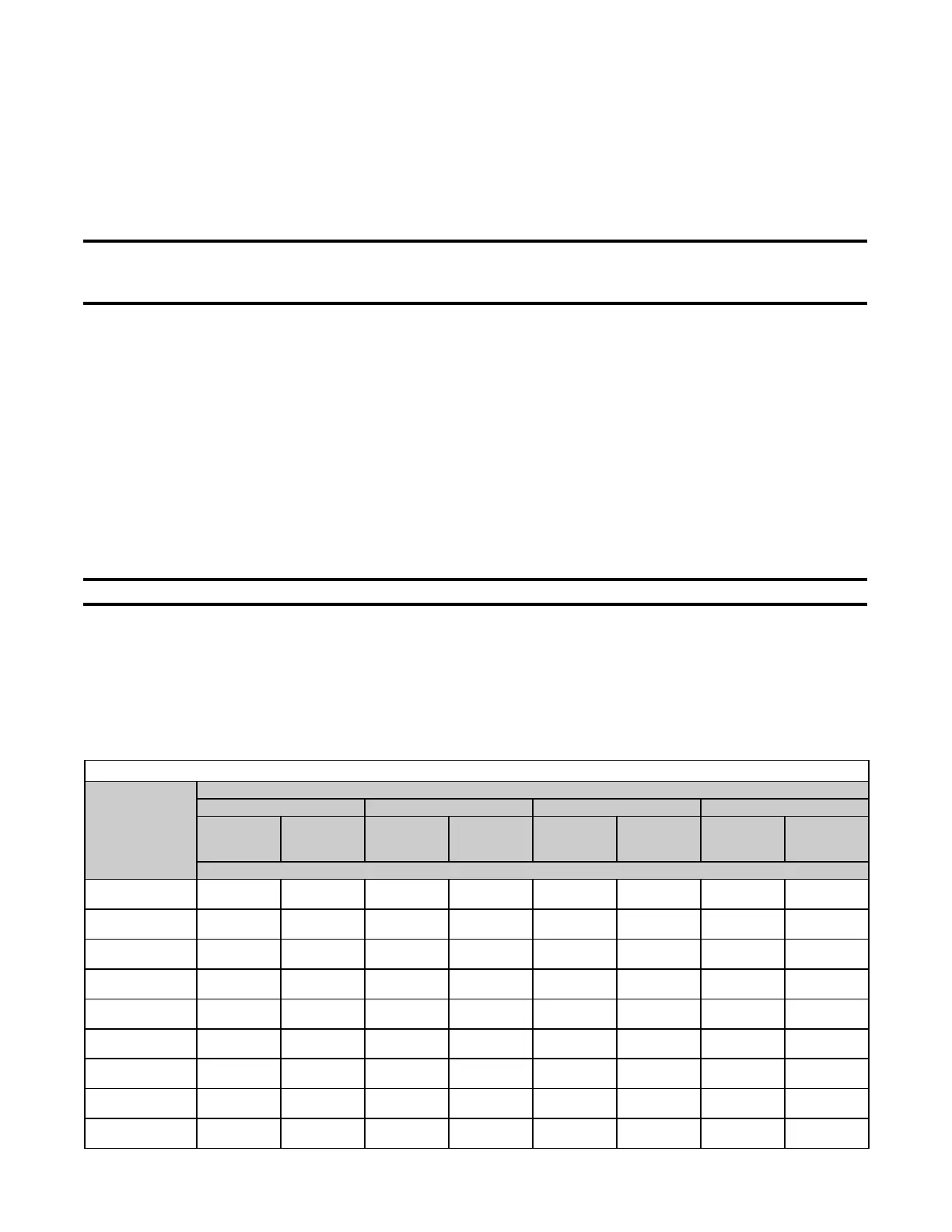
Table 24. Inputs and Capacities by Elevation in US
Elevation
(Feet (Meters))
Unit Size
130 180 260 310
Normal
Input
Thermal
Output
Capacity
Normal
Input
Thermal
Output
Capacity
Normal
Input
Thermal
Output
Capacity
Normal
Input
Thermal
Output
Capacity
BTUh
0–2000
(0–610)
131,000 121,830 175,000 159,250 260,000 239,200 305,000 277,550
2001–3000
(611–915)
123,140 114,520 164,500 149,695 244,400 224,848 286,700 260,897
3001–4000
(916–1220)
120,520 112,084 161,000 146,510 239,200 220,064 280,600 255,346
4001–5000
(1221–1525)
117,900 109,647 157,500 143,325 234,000 215,280 274,500 249,795
5001–6000
(1526–1830)
115,280 107,210 154,000 140,140 228,800 210,496 268,400 244,244
6001–7000
(1831–2135)
112,660 104,774 150,500 136,955 223,600 205,712 262,300 238,693
7001–8000
(2136–2440)
110,040 102,337 147,000 133,770 218,400 200,928 256,200 233,142
8001–9000
(2441–2745)
107,420 99,901 143,500 130,585 213,200 196,144 250,100 227,591
9001–10,000
(2746–3045)
104,800 97,464 140,000 127,400 208,000 191,360 244,000 222,040

 Loading...


