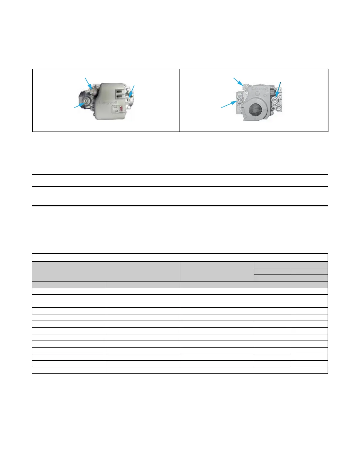
Figure 28. Gas Valves
3. Open manual valve and operate heater. Depress and hold door safety switch.
4. Cycle burner once or twice to properly seat adjustment spring in valve and observe manometer gauge to measure
outlet pressure of gas valve.
⚠ CAUTION ⚠
DO NOT bottom out the gas valve regulator screw. This can result in excessive overfire and heat
exchanger failure due to unregulated manifold pressure.
5. If manometer reading does not indicate that valve outlet pressure is in accordance with Table 23, remove cap
from regulator screw(s) (see Figure 28) and adjust pressure by turning regulator screw IN (clockwise) to increase
pressure or OUT (counterclockwise) to decrease pressure.
6. When manometer reading indicates that outlet pressure is in accordance with Table 23, disconnect manometer
and install cap(s) on regulator screw(s).
Table 23. Required Manifold (Outlet) Gas Pressure
Elevation Natural Gas
Unit Size
130, 260 180, 310
Propane
Feet Meters Manifold Pressure (IN WC)
US
0–2000 0–610 3.5 10.0 9.5
2001–3000 611–915 3.1 8.8 8.4
3001–4000 916–1220 3.0 8.5 8.0
4001- 5000 1221–1525 2.8 8.1 7.7
5001–6000 1526–1830 2.7 7.7 7.3
6001–7000 1831–2135 2.6 7.4 7.0
7001–8000 2136–2440 2.5 7.1 6.7
8001–9000 2441–2745 2.4 6.7 6.3
9001–10,000 2746–3045 2.2 6.4 6.0)
Canada
0–2000 0–610 3.5 10.0 9.5
2001–4500 611–1373 2.8 8.1 7.7
1/8-INCH OUTPUT
PRESSURE TAP
INLET
PRESSURE TAP
REGULATOR SCREW
UNIT SIZES 260 AND 310
UNIT SIZES 130 AND 180
1/8-INCH OUTLET
PRESSURE TAP
INLET
PRESSURE TAP
REGULATOR SCREW
ADJUSTMENTS—CONTINUED
Measure and Adjust Manifold (Outlet) Gas Pressure—Continued
Measure and Adjust Manifold Gas Pressure—Elevation ≤2,000 Feet (≤610 Meters)—Continued
44
I-UEZ (04-21) 1034347-0

 Loading...


