17
VZ-VZH-VZT-IOM (08-24) 1047121-A
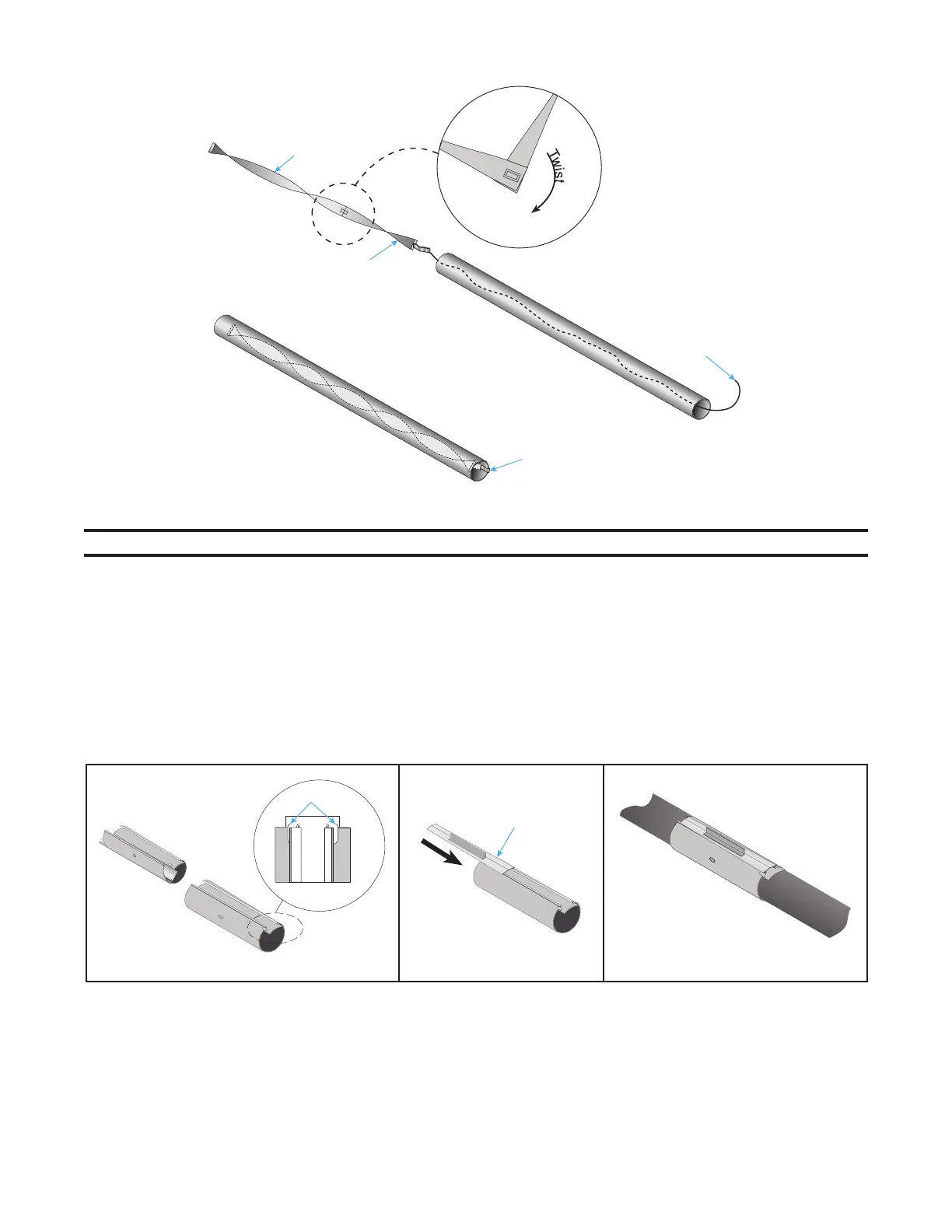
STRING
TAB
TABBED
SECTION
CONNECTOR
SECTION
Figure 8. Swirler Installation
NOTE: Couplings will slide over turbulator and swirler tabs.
4. Install coupling(s):
a. Close coupling—tabs positioned beneath guide rails (see Figure 9, DETAIL A).
b. Slide wide end of coupling lock bar into end of coupling opposite tabs until snug (see Figure 9, DETAIL B).
c. Slide each tube into coupling until end of each rests against internal pins of coupling.
d. Rotate coupling so that coupling lock bar is at 2 or 10 o’clock position.
e. Tighten coupling lock bar—tap with hammer as necessary—until positioned as shown in Figure 9, DETAIL
C. DO NOT OVERTIGHTEN.
f. Repeat steps 4a through 4e for each coupling.
Figure 9. Coupling Installation
5. Install vent adapter (see Figure 5) with seam on top and seal joint using high-temperature (≥550°F (≥288°C))
silicone sealant to prevent leakage of condensation. Refer to Vertical Venting section for exceptions to use of
vent adapter.
DETAIL A
DETAIL B
DETAIL C
TABS
COUPLING
LOCK BAR