– Version 1.2 – Status – Issued for use
Document Number – PRJ-TXM-MAN-001
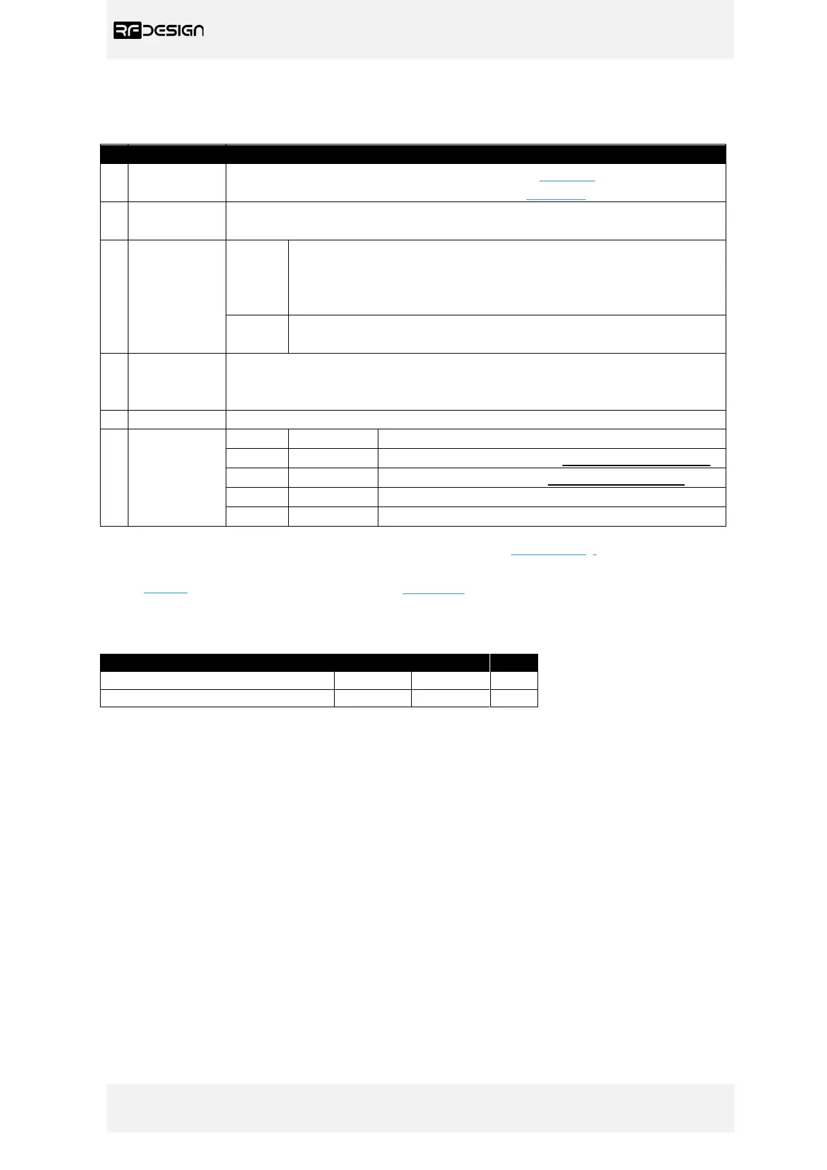
Table 1 - TXMOD Description
For information about antenna selection refer to section 5 in this document
or to the RFD 900x Modem datasheet linked in section 7.
The heatsink, visible through the top cover, is required for proper operation
and should not be covered while the unit is in use.
Blinks slowly a few times - establishing link to a Wi-Fi client.
Blinks rapidly for some time - flashing the modem firmware (using
‘spiffs.bin’ file explained in 3.2.2e)
Solid - device initialisation has completed
Blinking – RFD modem looking for a link
Solid – RFD modem bound to another modem
Press 5 times within 5 seconds to reset all Wi-Fi settings to default values.
(Red LED will turn off, blink 3 times and go solid after resetting default Wi-Fi
settings)
Mechanical clips to lock the TXMOD into the radio control socket.
RC and
TXMOD
Interface.
∗∗
Sends RC data into TXMOD.
6V supply positive terminal (not used by the module)
Positive battery terminal (supply for the module)
∗∗∗
∗
Green LED will be enabled after ‘First Run Wizard’ explained in section section 3.2.2 0.
∗∗
Interface between RC and TXMOD is done through a female 0.1” pitch connector.
∗∗∗
See Table 2 below for module supply ratings and section 6.1 for the relation between battery voltage and
current draw with different battery types.
Table 2 - TXMOD Supply Ratings
Supply Voltage (+Bat relative to GND)
∗
Rating for TXMOD with RFD modem set for maximum 1W transmit power measured at 5V supply.