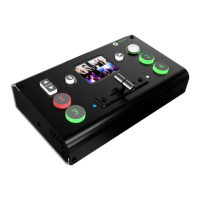
LED INDICATOR
The button 1/2/3/4/LOGO is lit when the signal or background input is selected for use.
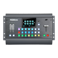
PST AREA
For indicating, user can not change the channel or set the size or position in this area.
LOGO
For switching from PGM to test pattern.
6/7/8/9/0
Each button is numbered and can be used as direct number entry when values such as
resolution and size.
PST AREA
For indicating, the button is lit when output the signal in PST channel.
For selecting, push any button to switch the PST signal.
For editing, (button light is lit -- the channel is used but can not be edited, button light is
flashing -- the channel can be edited, button light is off -- the channel is not selected.
MENU
Menu and exit reuse button.
SELECT/ENTER
Confirmation button.
LCD DISPLAY
Displays current status of the product, and for feature selections provides interactive
choices in conjunction with buttons on the Rear Panel.
 Loading...