EasyManua.ls Logo

Rheem 15 SEER Series - User Manual

Rheem 15 SEER Series
36 pages
Print Icon
To Next Page IconTo Next Page
Loading...
15 SEER SERIES
HEAT PUMPS
1
1
⁄2 - 5 TONS FEATURING
EARTH-FRIENDLY R-410A REFRIGERANT R-410
RECOGNIZE THIS SYMBOL AS AN INDICATION OF IMPORTANT SAFETY INFORMATION!
!
DO NOT DESTROY THIS MANUAL
PLEASE READ CAREFULLY AND KEEP IN A SAFE PLACE FOR FUTURE REFERENCE BY A SERVICEMAN
THESE INSTRUCTIONS ARE INTENDED AS AN AID TO
QUALIFIED, LICENSED SERVICE PERSONNEL FOR
PROPER INSTALLATION, ADJUSTMENT AND OPERATION
OF THIS UNIT. READ THESE INSTRUCTIONS THOROUGHLY
BEFORE ATTEMPTING INSTALLATION OR OPERATION.
FAILURE TO FOLLOW THESE INSTRUCTIONS MAY RESULT
IN IMPROPER INSTALLATION, ADJUSTMENT, SERVICE OR
MAINTENANCE POSSIBLY RESULTING IN FIRE, ELECTRICAL
SHOCK, PROPERTY DAMAGE, PERSONAL INJURY OR
DEATH.
WARNING
!
ISO 9001:2008
92-20522-80-03
SUPERSEDES 92-20522-80-02
INSTALLATION INSTRUCTIONS

Table of Contents

Question and Answer IconNeed help?

Do you have a question about the Rheem 15 SEER Series and is the answer not in the manual?

Overview

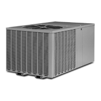
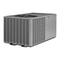
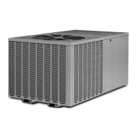
This document provides installation instructions for a 15 SEER Heat Pump, specifically the Earth-Friendly R-410A Refrigerant model, available in 1.5 to 5-ton capacities. The manual emphasizes safety information, general product details, installation procedures, and troubleshooting guidelines.

Function Description:

The device is a 15 SEER (Seasonal Energy Efficiency Ratio) heat pump designed for residential and light commercial heating and cooling applications. It utilizes R-410A refrigerant, an environmentally friendly alternative. The system is designed to provide efficient temperature control for indoor spaces by transferring heat between the indoor and outdoor environments.

Important Technical Specifications:

  • SEER Rating: 15 SEER, indicating high energy efficiency.
  • Capacity: Available in 1.5, 2, 2.5, 3, 3.5, 4, and 5-ton models.
  • Refrigerant: R-410A, a non-ozone-depleting refrigerant.
  • Electrical Data:
    • Voltage: Primarily 1-phase, 208/230V.
    • Minimum Circuit Ampacity (MCA): Varies by model, e.g., 13/13 for 1.5-ton, 26/26 for 4-ton, and 30/30 for 5-ton.
    • Maximum Fuse or HACR Breaker: Varies by model, e.g., 15/15 for 1.5-ton, 35/35 for 4-ton, and 50/50 for 5-ton.
    • Compressor RLA (Rated Load Amps): Varies by model, e.g., 9.9 for 1.5-ton, 19.9/19.9 for 4-ton, and 21.4/21.4 for 5-ton.
  • Physical Dimensions (Outdoor Unit):
    • Height ("H"): Varies from 26.25 inches (666.7 mm) for smaller units to 35.375 inches (898.5 mm) for larger units.
    • Length ("L"): 27.625 inches (701.6 mm) for smaller units, 31.625 inches (803.2 mm) for larger units.
    • Width ("W"): 27.625 inches (701.6 mm) for smaller units, 31.625 inches (803.2 mm) for larger units.
    • Air Discharge: Allow 60 inches (1524 mm) minimum clearance.
    • Air Inlets: Louvered panels allow 6 inches (152.4 mm) minimum clearance.
    • Service Access: Allow 24 inches (609.6 mm) minimum clearance.
  • Refrigerant Line Length: Maximum interconnecting line length is 150 feet (45.7 m). Additional compressor oil is not required for any length up to 150 feet.
  • Vertical Separation: Maximum vertical separation is 150 feet (45.7 m).
  • Tubing Connections: Uses "L" type copper refrigeration tubing.
  • Defrost Control: Features enhanced defrost control with diagnostic codes.
  • Crankcase Heater: Recommended for all models to prevent refrigerant migration during off-cycle operation.

Usage Features:

  • Installation Flexibility: Can be installed on a flat roof or slab, provided adequate support and clearance. Recommended elevated installation on a base pad (concrete or other suitable material) to prevent snow/ice buildup and ensure proper drainage.
  • Quiet Operation: Designed with features to minimize operating noise.
  • Corrosion Protection: The unit incorporates several features to resist corrosion, including pre-coated steel, galvanized steel, and baked enamel finishes. It is recommended to avoid installing the unit near corrosive environments (e.g., salt spray, sulfur, chlorine).
  • Serviceability: Designed for ease of service with accessible components and diagnostic features. The control board includes LEDs for troubleshooting.
  • Thermostat Compatibility: Compatible with standard heat pump thermostats. A 24-volt, 40 VA minimum transformer is required for the control circuit.
  • Demand Defrost Control: Utilizes a printed circuit board assembly with solid-state control devices to optimize defrost cycles, improving efficiency and performance.
  • High/Low Pressure Control: Includes both high and low-pressure controls for system protection.
  • Shipping Strap Removal: A crucial step during installation is to remove the plastic shipping strap from the base of the unit to prevent increased internal tubing stress.

Maintenance Features:

  • Regular Cleaning: Frequent washing of the cabinet, fan blade, and coil with fresh water is recommended to remove dirt and other contaminants. Regular cleaning and waxing of the cabinet with an automobile polish will provide additional protection.
  • Coil Cleaning: A liquid cleaner may be used several times a year to remove matter that will not wash off with water.
  • Filter Maintenance: Regular checking and replacement of indoor unit filters are essential for maintaining airflow and system efficiency.
  • Leak Testing: After installation, the system must be properly evacuated and charged, and a halogen leak detector should be used to check for leaks.
  • Electrical Checks: Regular checks of electrical connections, voltage, and current are important for safe and reliable operation.
  • Troubleshooting Charts: The manual includes detailed troubleshooting flow charts for electrical checks, cooling, heating, and defrost issues, as well as a service analyzer chart for compressor overheating symptoms. These charts guide technicians through a logical process to diagnose and resolve common problems.
  • Refrigerant Charge Verification: The system charge should be checked against the Charging Chart inside the access panel cover. Refrigerant charge adjustments should be made based on subcooling measurements.
  • Component Replacement: The manual provides guidance on replacing components, emphasizing the use of authorized parts and qualified service personnel.
  • Wiring Diagrams: Detailed wiring diagrams for both PSC motor and ECM motor enhanced defrost control are provided to aid in electrical troubleshooting and maintenance.

Rheem 15 SEER Series Specifications

General IconGeneral
BrandRheem
Model15 SEER Series
CategoryHeat Pump
LanguageEnglish

Related product manuals