Do you have a question about the Rheem A17 Series and is the answer not in the manual?
Recognizes safety symbols and provides warnings regarding proper installation, adjustment, and operation.
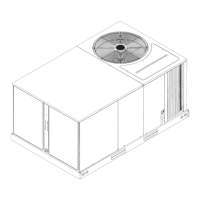
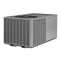
Details the (-)A17 series condensing units' compatibility with EcoNet™ systems and conventional controls.
Specifies procedures for verifying efficiency ratings based on AHRI standards.
Emphasizes critical factors for safety, reliability, and efficiency in installation.
Outlines the process for specifying HVAC equipment based on heat gain calculations.
Highlights the necessity of matching indoor and outdoor units for optimal performance.
Instructs on inspecting received units for shipping damage and verifying components.
Provides guidelines for initial compressor operation to ensure proper break-in.
Explains the model number structure and lists available unit configurations.
Presents detailed electrical and physical specifications for the unit models.
Lists required tools and specifications for installing R-410A models.
Details site selection criteria, including clearances and operational considerations.
Covers methods for mounting the unit, including high wind and seismic tie-down.
Provides guidelines for selecting and sizing refrigerant line sets for optimal performance.
Offers practices for installing refrigerant tubing, including connections and support.
Describes the procedure for initial leak testing of the system using nitrogen.
Details the critical process of evacuating air and moisture from the system.
Instructs on performing final leak detection after evacuation.
Covers wiring for EcoNet™ communication and conventional thermostat controls.
Specifies requirements for connecting line voltage power to the unit.
Details the importance and procedure for permanent unit grounding.
Provides an overview of the steps for starting up the system and verifying components.
Guides on powering up the system and verifying communication between components.
Instructions for configuring the EcoNet™ Control Center before system startup.
Details setting the thermostat and initial system operation for verification.
Explains how to verify and adjust indoor air-flow for optimal system performance.
Describes how to check and adjust the refrigerant charge against the charging chart.
Guides on connecting gauges and temperature probes for charging measurements.
Details calculating and adding refrigerant charge based on line set length and weight.
Offers an optional method for preliminary charging using system pressures.
Explains the final charging adjustment using liquid subcooling measurements.
Final steps to complete installation, including disconnecting hoses and restoring power.
Describes the sequence of operation for the cooling mode, including stage transitions.
Explains the operation of the On-Demand Dehumidification feature with EcoNet™ systems.
Details the Copeland Ultratech 2-stage scroll compressors used in the units.
Describes the capacitor types used for compressors and fan motors in different models.
Explains the single-pole contactor used to control the compressor.
Discusses the need for and function of crankcase heaters for compressors.
Introduces the TSODC, its interface, and its role in system communication and control.
Details the function and settings of high and low pressure controls for compressor protection.
Explains the outdoor ambient temperature sensor and its connection to the TSODC.
Describes the design of the outdoor fan blade for efficiency and quiet operation.
Details the types of outdoor fan motors used in different models (ECM vs. PSC).
Describes the low ambient kit for maintaining system balance at lower outdoor temperatures.
Details the hard start kit for special cases to reduce light dimming during startup.
Lists part numbers for compressor crankcase heaters for 2-ton models.
Provides part numbers for compressor sound enclosures for 2, 3, 4, and 5 ton models.
Explains how to enter and use test modes and fault recall functions on the TSODC.
Lists and describes the diagnostic codes displayed by the 7-segment LEDs on the control.
A flowchart to guide electrical troubleshooting steps for unit issues.
A flowchart to guide mechanical troubleshooting steps for cooling problems.
Provides resistance charts for checking outdoor temperature sensors.
A table listing common symptoms, possible causes, and remedies for unit malfunctions.
Provides troubleshooting tips for cooling mode indicators like pressure, superheat, and subcooling.
Details the recommended procedure for cleaning the outdoor coil annually.
Provides guidance on cleaning and waxing the exterior cabinet.
Explains that outdoor fan motors are pre-lubricated and do not require additional oiling.
States that replacement parts must be identical or approved alternates to original parts.
Presents the wiring diagram for 2, 4, and 5 ton models with ECM fan motors.
Presents the wiring diagram for 3 ton models with PSC fan motors.
| Type | Heat Pump |
|---|---|
| Heating Capacity | 18, 000 - 60, 000 BTU/h |
| Cooling Capacity | 18, 000 - 60, 000 BTU/h |
| Refrigerant | R-410A |
| Voltage | 208/230V |
| Stages | Single-Stage |
| Series | A17 Series |